Subaru Impreza 3 / Impreza WRX / Impreza WRX STI. Manual - part 173
 

  Index      Subaru     Subaru Impreza 3 / Impreza WRX / Impreza WRX STI - service repair manual 2008-2014 year


Search            


Content   ..  171  172  173  174   ..


Subaru Impreza 3 / Impreza WRX / Impreza WRX STI. Manual - part 173


ME(w/o STI)-73

Cylinder Head

MECHANICAL

(4) Set the ST2 on valve spring.

ST2 499718000

VALVE SPRING REMOVER

(5) Compress the valve spring and fit the valve

spring retainer key.

(6) After installing, tap the valve spring retainers

lightly with a plastic hammer for better seating.

2) Apply oil to the surface of valve lifter.

3) Install the valve lifter.

E: INSPECTION

1. CYLINDER HEAD

1) Check  for  cracks  or  damage.  Use  liquid  pene-

trant tester on the important sections to check for

fissures. Check that there are no marks of gas leak-

ing or water leaking on gasket installing surface.

2) Measure the warping of the cylinder head sur-

face that mates with cylinder block using a straight

edge (A) and thickness gauge (B).

If the warping exceeds the limit, correct the surface

by grinding it with a surface grinder.
Warping limit:

0.035 mm (0.0014 in)

Grinding limit:

0.3 mm (0.012 in)

Standard height of cylinder head:

127.5 mm (5.02 in)

NOTE:

Uneven  torque  for  the  cylinder  head  bolts  can

cause warpage. When reinstalling, pay special at-

tention to the torque so as to tighten evenly.

2. VALVE SEAT

Inspect  the  intake  and  exhaust  valve  seats,  and

correct the contact surfaces with a valve seat cutter

if they are defective or when valve guides are re-

placed.
Contacting width W between valve and valve 

seat:
Standard

Intake

0.6 — 1.4 mm (0.024 — 0.055 in)

Exhaust

1.2 — 1.8 mm (0.047 — 0.071 in)

3. VALVE GUIDE

1) Check the clearance  between valve guide  and

valve stem. The clearance can be checked by mea-

suring  respectively  the  outer  diameter  of  valve

stem with a micrometer and the inner diameter of

valve guide with a caliper gauge.
Clearance between the valve guide and valve 

stem:
Standard

Intake

0.030 — 0.057 mm (0.0012 — 0.0022 in)

Exhaust

0.040 — 0.067 mm (0.0016 — 0.0026 in)

ME-05003

ST1

ST2

ME-00126

(A)

(B)

ME-04721

W

ME-00287

ME(w/o STI)-74

Cylinder Head

MECHANICAL

2) If the clearance between valve guide and valve

stem  exceeds  the  standard,  replace  the  valve

guide or valve itself, whichever shows the greater

amount of wear or damage. See the following pro-

cedure for valve guide replacement.
Valve guide inner diameter:

6.000 — 6.012 mm (0.2362 — 0.2367 in)

Valve stem outer diameters:

Intake

5.955 — 5.970 mm (0.2344 — 0.2350 in)

Exhaust

5.945 — 5.960 mm (0.2341 — 0.2346 in)

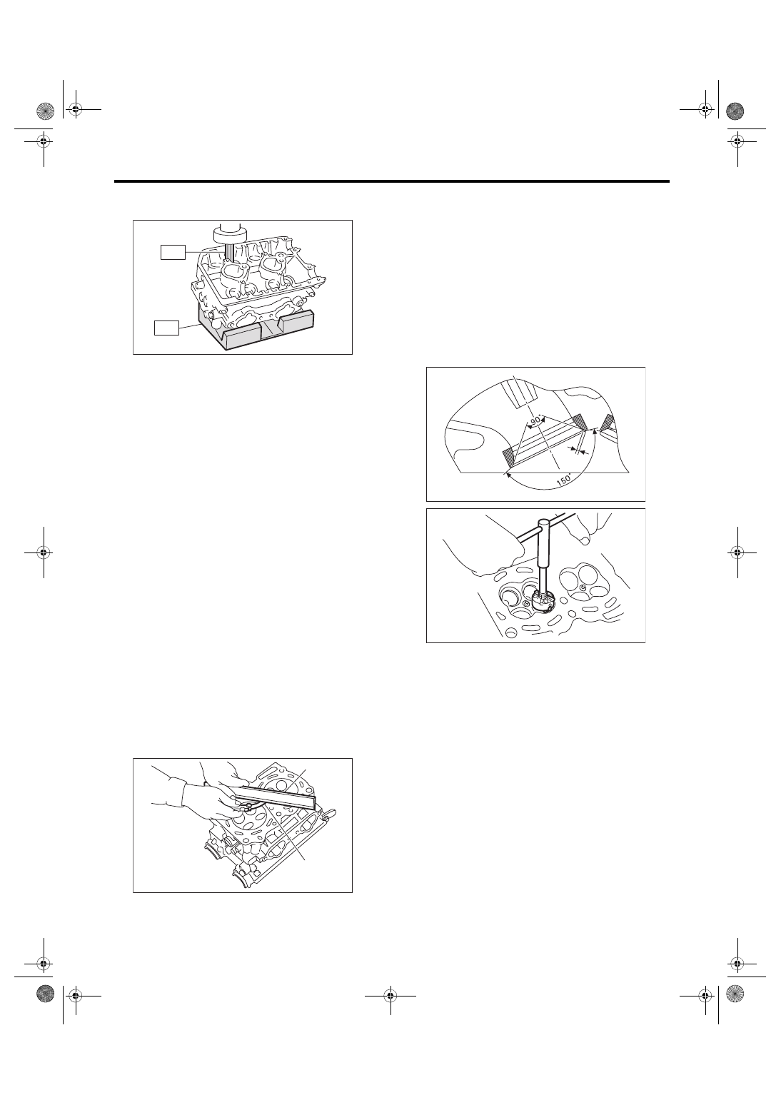
(1) Place  the  cylinder  head  on  ST1  with  the

combustion  chamber  upward  so  that  valve

guides fit the holes in ST1.

(2) Insert the ST2 into valve guide and press it

down to remove the valve guide.

ST1 498267600

CYLINDER HEAD TABLE

ST2 499767200

VALVE GUIDE REMOVER

(3) Turn  the  cylinder  head  upside  down  and

place the ST as shown in the figure.

ST 18251AA020 VALVE GUIDE ADJUSTER

(4) Before  installing  a  new  valve  guide,  make

sure that neither scratches nor damages exist

on the inner surface of valve guide holes in cyl-

inder head.

(5) Put a new valve guide, coated with sufficient

oil, in the cylinder head, and insert the ST1 into

valve guide. Press in until the valve guide upper

end is flush with the upper surface of ST2.

ST1 499767200

VALVE GUIDE REMOVER

ST2 18251AA020

VALVE GUIDE ADJUSTER

(6) Check  the  valve  guide  protrusion  amount

“L”.

Valve guide protrusion amount L:

15.8 — 16.2 mm (0.622 — 0.638 in)

(7) Ream  the  inside  of  valve  guide  using  ST.

Put  the  ST  in  valve  guide,  and  rotate  the  ST

slowly clockwise while pushing it lightly. Bring

the ST back while rotating it clockwise.

NOTE:

• Apply engine oil to the ST when reaming.

• If the inner surface of valve guide is damaged,

the  edge  of  ST  should  be  slightly  ground  with  oil

stone.

• If the inner surface of valve guide becomes lus-

trous and the ST does not chip, use a new ST or

remedy the ST.

ST 499767400

VALVE GUIDE REAMER

ME-05004

ST1

ST2

ST

ME-04107

ME-00130

ST1

ST2

L

ME-04522

ME-04393

ST

ME(w/o STI)-75

Cylinder Head

MECHANICAL

(8) After reaming, clean the valve guide to re-

move chips.

(9) Recheck  the  contact  condition  between

valve and  valve seat  after replacing  the valve

guide.

4. INTAKE AND EXHAUST VALVE

1) Inspect the flange of valve and valve stem, and

replace the valve with a new part if damaged, worn,

deformed, or if dimension “H” in the figure is out-

side of the specified limit.
Head edge thickness H:
Standard

Intake (A)

1.0 — 1.4 mm (0.039 — 0.055 in)

Exhaust (B)

1.3 — 1.7 mm (0.051 — 0.067 in)

2) Put a small amount of grinding compound on the

valve seat surface, and lap the valve and valve seat

surface. Replace with a new valve oil seal after lap-

ping.
NOTE:

It  is  possible  to  differentiate  between  the  intake

valve and the exhaust valve by their overall length.
Valve overall length:

Intake

104.4 mm (4.110 in)

Exhaust

104.65 mm (4.1201 in)

5. VALVE SPRING

1) Check the valve springs for damage, free length,

and  tension.  Replace  the  valve  spring  if  it  is  not

within the standard value presented in the table.

2) To measure the squareness of the valve spring,

stand the valve spring on a surface plate and mea-

sure its deflection at the top of the valve spring us-

ing a try square.

ME-04825

(B)

(A)

H

H

Free length

mm (in) 47.32 (1.863)

Tension/spring 
height
N (kgf, lb)/mm (in)

Set

205 — 235 (20.9 — 24.0, 
46.1 — 52.8)/36.0 (1.417)

Lift

426 — 490 (43.4 — 50.0, 
95.8 — 110)/26.50 (1.041)

Squareness

2.5°, 2.1 mm (0.083 in) or less

ME-00283

ME(w/o STI)-76

Cylinder Head

MECHANICAL

6. INTAKE AND EXHAUST VALVE OIL 

SEAL

1) For the following, replace the oil seal with a new

part. See the procedure 2) and subsequent for re-

placement procedures.

• When the lip is damaged.

• When the spring is out of the specified position.

• When  readjusting  the  surfaces  of  valve  and

valve seat.

• When replacing the valve guide.

2) Place the cylinder head on ST1, and use ST2 to

press-fit the oil seal.

ST1 498267600

CYLINDER HEAD TABLE

ST2 498857100

VALVE OIL SEAL GUIDE

NOTE:

• Apply engine oil to oil seal before press-fitting.

• When press-fitting the oil seal, do not use a ham-

mer to strike in.

• The intake valve oil seals and exhaust valve oil

seals are distinguished by their colors.
Color of rubber part:

Intake [Gray]

Exhaust [Green]

7. VALVE LIFTER

1) Check the valve lifter visually.

2) Measure the outer diameter of valve lifter.
Outer diameter of valve lifter:

Standard

34.959 — 34.975 mm (1.3763 — 1.3770 in)

3) Measure the inner diameter of valve lifter mating

surface on cylinder head.
Valve lifter mating surface inner diameter:

Standard

34.994 — 35.016 mm (1.3777 — 1.3786 in)

4) Check  the  clearance  between  valve  lifter  and

valve  lifter  mating  surface.  The  clearance  can  be

checked by measuring the outer diameter of valve

lifter and the inner diameter of valve lifter. If it ex-

ceeds the standard or offset wear occurs, replace

the cylinder head.
Valve lifter and valve lifter mating surface clear-

ance:

Standard

0.019 — 0.057 mm (0.0007 — 0.0022 in)

ME-00133

ST2

ME-00134

ME-00135


Content   ..  171  172  173  174   ..