Subaru Impreza 3 / Impreza WRX / Impreza WRX STI. Manual - part 162
 

  Index      Subaru     Subaru Impreza 3 / Impreza WRX / Impreza WRX STI - service repair manual 2008-2014 year


Search            


Content   ..  160  161  162  163   ..


Subaru Impreza 3 / Impreza WRX / Impreza WRX STI. Manual - part 162


ME(w/o STI)-29

Engine Assembly

MECHANICAL

9. Engine Assembly

A: REMOVAL

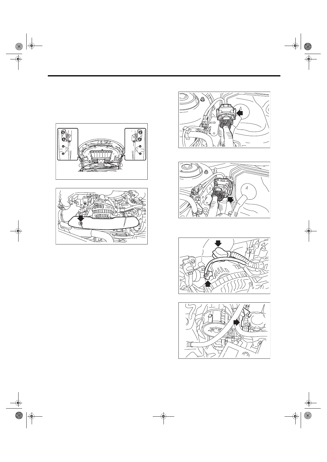
1) Change the bolt installation position from (A) to

(B), then open the front hood completely.
Tightening torque:

7.5 N·m (0.8 kgf-m, 5.5 ft-lb)

2) Remove the V-belt covers.

3) Collect the refrigerant from A/C system. <Ref. to

AC-19, Refrigerant Recovery Procedure.>

4) Release the fuel pressure. <Ref. to FU(w/o STI)-

65, RELEASING OF FUEL PRESSURE, PROCE-

DURE, Fuel.>

5) Remove  the  battery.  <Ref.  to  SC(STI)-27,  RE-

MOVAL, Battery.>

6) Open the fuel filler lid and remove the fuel filler

cap.

7) Remove the air intake duct and air cleaner case.

<Ref.  to  IN(w/o  STI)-10,  REMOVAL,  Air  Intake

Duct.>  <Ref.  to  IN(w/o  STI)-8,  REMOVAL,  Air

Cleaner Case.>

8) Remove the intercooler. <Ref. to IN(w/o STI)-12,

REMOVAL, Intercooler.>

9) Remove the radiator. <Ref. to CO(w/o STI)-19,

REMOVAL, Radiator.>

10) Remove the coolant filler tank. <Ref. to CO(w/o

STI)-28, REMOVAL, Coolant Filler Tank.>

11) Disconnect  the  bulkhead  harness  connectors

from the engine harness connectors.

12) Remove  the  engine  harness  connector  from

the engine harness bracket.

13) Disconnect the following connectors and termi-

nals.

(1) Generator connector and terminal

(2) Secondary air pump connector

ME-03387

(A)

(B)

(A)

(B)

ME-03386

FU-06604

FU-06605

ME-04654

ME-04195

ME(w/o STI)-30

Engine Assembly

MECHANICAL

14) Disconnect  the  connector  (A)  from  the  A/C

compressor, and remove the clip (B) securing the

generator cord.

15) Disconnect the following hoses.

(1) A/C  pressure  hose  <Ref.  to  AC-41,  RE-

MOVAL, Hose and Pipe.>

(2) Brake booster vacuum hose

(3) Heater inlet hose and heater outlet hose

16) Remove the power steering pump.

(1) Remove the front side belts. <Ref. to ME(w/

o STI)-38, FRONT SIDE BELT, REMOVAL, V-

belt.>

(2) Disconnect the connector from power steer-

ing pump switch.

(3) Remove the power steering pump from the

engine.

(4) Place the power steering pump on the right

side wheel apron.

17) Remove  the  center  exhaust  pipe.  <Ref.  to

EX(STI)-8, REMOVAL, Center Exhaust Pipe.>

18) Remove  the  turbocharger.  <Ref.  to  IN(w/o

STI)-14, REMOVAL, Turbocharger.>

19) Remove the joint pipe and front exhaust pipe.

<Ref.  to  EX(STI)-12,  REMOVAL,  Joint  Pipe.>

<Ref.  to  EX(STI)-6,  REMOVAL,  Front  Exhaust

Pipe.>

20) Disconnect  the  ground  cable  on  the  engine

side.

ME-04967

(B)

(A)

(B)

ME-04196

ME-04197


FU-04598

ME-03617

ME-03702

ME(w/o STI)-31

Engine Assembly

MECHANICAL

21) Remove the bolts and nuts which hold the low-

er side of transmission to the engine.

22) Remove  the  nuts  which  secure  the  engine

mounting to the front crossmember.

23) Lower the vehicle.

24) Remove the pitching stopper.

25) Attach ST to the fuel delivery pipe and push ST

in the direction of arrow mark to disconnect the fuel

delivery hose.

ST 42099AE000 QUICK CONNECTOR RE-

LEASE

CAUTION:

• Be careful not to spill fuel.

• Catch the fuel from hoses using a container

or cloth.

26) Disconnect the fuel return hose using the ST.

ST 18371AA000 CONNECTOR REMOVER
CAUTION:

• Be careful not to spill fuel.

• Catch the fuel from hoses using a container

or cloth.

(1) Attach ST to the fuel return pipe as shown in

the figure.

MT-00077

ME-03703

LU-02462

(A) Fuel delivery hose
(B) Fuel return hose

(C) Evaporation hose

ME-04968

(B) (C)

(A)

ST

ME-04969

ST

ME(w/o STI)-32

Engine Assembly

MECHANICAL

(2) Insert the front side of ST into the quick con-

nector.

(3) Insert the back side of ST into the quick con-

nector  and  push  ST  in  the  direction  of  arrow

mark to disconnect the fuel return hose.

27) Remove the clip and disconnect the evapora-

tion hose from the fuel pipe.

28) Support  the  engine  with  a  lifting  device  and

wire ropes.

29) Support the transmission with a garage jack.
CAUTION:

Be  sure  to  perform  this  procedure  to  prevent

the  transmission  from  lowering  by  its  own

weight.

30) Separation of engine and transmission
CAUTION:

Before  removing  the  engine  away  from  trans-

mission,  check  to  be  sure  no  work  has  been

overlooked.

(1) Remove the starter. <Ref. to SC(STI)-8, RE-

MOVAL, Starter.>

(2) Remove the bolts which hold the upper side

of the transmission to the engine.

31) Remove the engine from the vehicle.
NOTE:

Be  careful  not  to  damage  adjacent  parts  or  body

panels with crank pulley, oil level gauge, etc.

(1) Slightly raise the engine.

(2) Raise the transmission with garage jack.

(3) Move  the  engine  horizontally  until  main

shaft is withdrawn from clutch cover.

(4) Slowly move the engine away from engine

compartment.

32) Remove the engine mounting from the engine.

ME-04970

ST

ME-04971

ST

FU-04611

LU-00222

(A) Transmission
(B) Garage jack

ME-04959

(B)

(A)

MT-01524


Content   ..  160  161  162  163   ..