Subaru Impreza 3 / Impreza WRX / Impreza WRX STI. Manual - part 160


  Index      Subaru     Subaru Impreza 3 / Impreza WRX / Impreza WRX STI - service repair manual 2008-2014 year


Search            


Content   ..  158  159  160  161   ..


Subaru Impreza 3 / Impreza WRX / Impreza WRX STI. Manual - part 160


ME(w/o STI)-21

Ignition Timing

MECHANICAL

4. Ignition Timing

A: INSPECTION

CAUTION:

After warming-up, engine becomes very hot. Be

careful not to burn yourself at measurement.

1. METHOD WITH SUBARU SELECT MON-

ITOR

1) Before  checking  the  ignition  timing,  check  the

following item:

(1) Check the air cleaner element is free from

clogging, spark plugs are in good condition, and

hoses are connected properly.

(2) Check  the  malfunction  indicator  light  does

not illuminate.

2) Warm up the engine.

3) Read  the  ignition  timing  using  Subaru  Select

Monitor.  <Ref.  to  EN(H4DOTC)(diag)-41,  READ

CURRENT  DATA  FOR  ENGINE  (NORMAL

MODE), OPERATION, Subaru Select Monitor.>
NOTE:

If ignition timing is out of standard, check the igni-

tion control system. Refer to “Engine Control Sys-

tem”.  <Ref.  to  EN(H4DOTC)(diag)-2,  Basic

Diagnostic Procedure.>
Ignition timing [BTDC/rpm]:

Standard

12°

±

10°/700

2. METHOD WITH TIMING LIGHT

1) Before  checking  the  ignition  timing,  check  the

following item:

(1) Check the air cleaner element is free from

clogging, spark plugs are in good condition, and

hoses are connected properly.

(2) Check  the  malfunction  indicator  light  does

not illuminate.

2) Warm up the engine.

3) Stop the engine, and turn the ignition switch to

OFF.

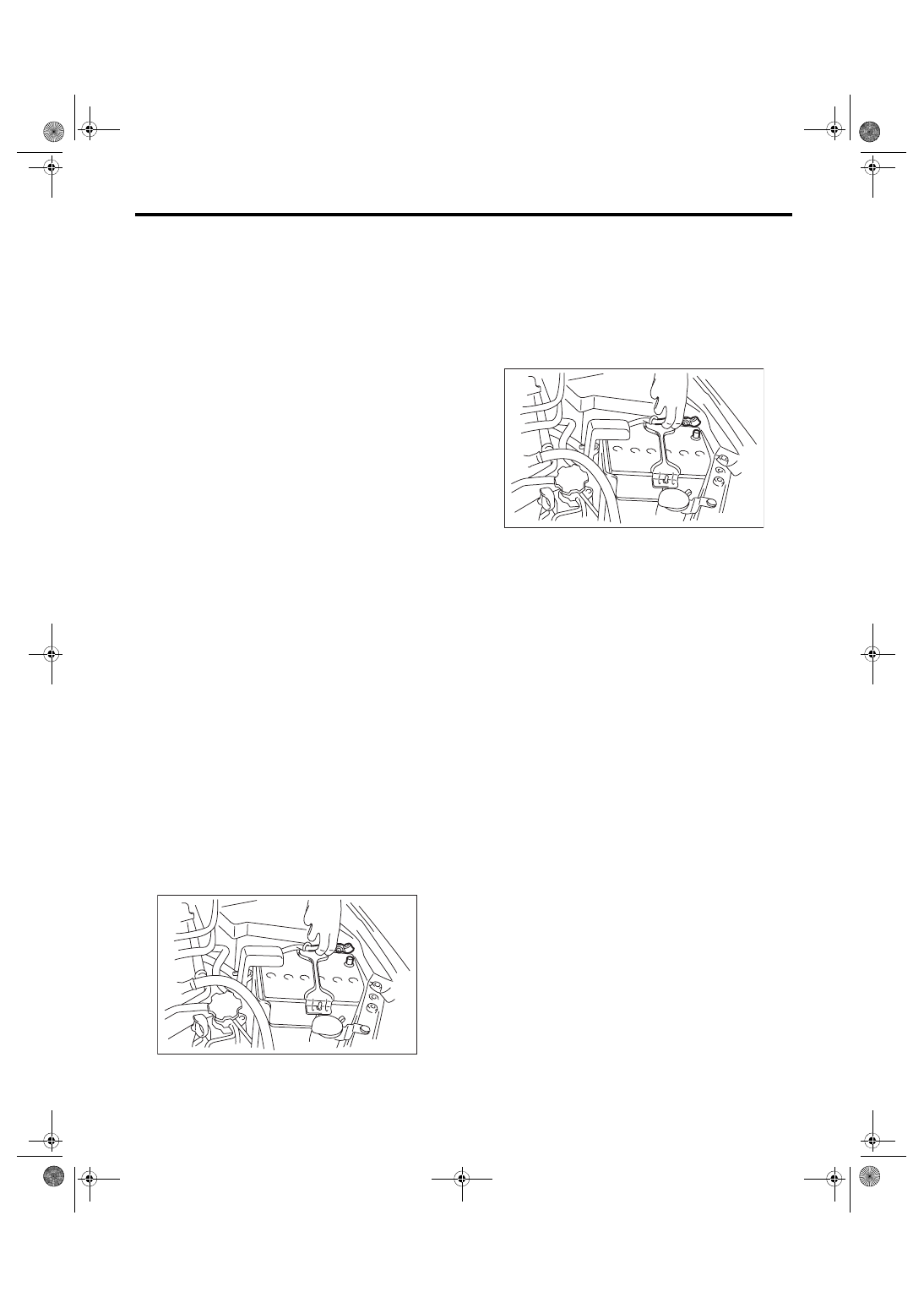
4) Disconnect the ground cable from battery.

5) Remove the air intake duct. <Ref. to IN(w/o STI)-

10, REMOVAL, Air Intake Duct.>

6) Remove  the  air  cleaner  case.  <Ref.  to  IN(w/o

STI)-8, REMOVAL, Air Cleaner Case.>

7) Connect the timing light to the power wire of #1

ignition coil.

8) Install the air cleaner case. <Ref. to IN(w/o STI)-

8, INSTALLATION, Air Cleaner Case.>

9) Connect the battery ground terminal.

10) Start  the  engine,  turn  the  timing  light  to  the

crank pulley, and check the ignition timing through

the timing belt cover gauge.
NOTE:

If ignition timing is out of standard, check the igni-

tion control system. Refer to “Engine Control Sys-

tem”.  <Ref.  to  EN(H4DOTC)(diag)-2,  Basic

Diagnostic Procedure.>
Ignition timing [BTDC/rpm]:

Standard

12°

±

10°/700

11) After inspection, install the related parts in the

reverse order of removal.

IN-00203

IN-00203

ME(w/o STI)-22

Intake Manifold Vacuum

MECHANICAL

5. Intake Manifold Vacuum

A: INSPECTION

1) Warm up the engine.

2) Remove the intercooler. <Ref. to IN(w/o STI)-12,

REMOVAL, Intercooler.>

3) Disconnect the brake booster vacuum hose from

the intake manifold, and attach the vacuum gauge.

4) Install  the  intercooler.  <Ref.  to  IN(w/o  STI)-12,

INSTALLATION, Intercooler.>

5) Keep the engine at idle speed and read the vac-

uum gauge indication.
NOTE:

Condition of engine inside can be diagnosed by ob-

serving the behavior of the vacuum gauge needle

as described in table below.
Intake manifold vacuum (at idling, A/C OFF):

Standard

–70.6 kPa (–530 mmHg, –20.85 inHg) or 

more

6) After  inspection,  install  the  related  parts  in  the

reverse order of removal.

ME-03897

Diagnosis of engine condition by inspection of intake manifold vacuum

Vacuum gauge needle behavior

Possible engine condition

1. Needle is steady but lower than standard value. This tendency 
becomes more evident as engine temperature rises.

Leakage around intake manifold gasket, disconnection or 
damage of vacuum hose

2. Needle intermittently drops to position lower than standard value. Leakage around cylinder
3. Needle drops suddenly and intermittently from standard value.

Sticky valve

4. When engine speed is gradually increased, needle begins to 
vibrate rapidly at certain speed, and then vibration increases as 
engine speed increases.

Weak or broken valve springs

5. Needle vibrates above and below standard value in narrow range. Defective ignition system

ME(w/o STI)-23

Engine Oil Pressure

MECHANICAL

6. Engine Oil Pressure

A: INSPECTION

1) Disconnect the ground cable from battery.

2) Remove  the  oil  pressure  switch.  <Ref.  to

LU(STI)-22, REMOVAL, Oil Pressure Switch.>

3) Install the oil pressure gauge to cylinder block.

4) Connect the battery ground terminal.

5) Start the engine, and check the oil pressure.
NOTE:

• Standard value is based on an engine oil temper-

ature of 80°C (176°F).

• If the oil pressure is out of specification, check oil

pump,  oil  filter  and  lubrication  line.  <Ref.  to

LU(STI)-32,  INSPECTION,  Engine  Lubrication

System Trouble in General.>

• If  the  oil  pressure  warning  light  is  ON  and  oil

pressure is within specification, check the oil pres-

sure  switch.  <Ref.  to  LU(STI)-32,  INSPECTION,

Engine Lubrication System Trouble in General.>
Engine oil pressure:

Standard

98 kPa (1.0 kgf/cm

2

, 14 psi) or more (at 600 

rpm)

294 kPa (3.0 kgf/cm

2

, 43 psi) or more (at 

5,000 rpm)

6) After  inspection,  install  the  related  parts  in  the

reverse order of removal.

IN-00203

ME-03698

IN-00203

ME(w/o STI)-24

Fuel Pressure

MECHANICAL

7. Fuel Pressure

A: INSPECTION

CAUTION:

• Before removing the fuel pressure gauge, re-

lease the fuel pressure.

• Be careful not to spill fuel.

• Catch the fuel from hoses using a container

or cloth.

1) Release the fuel pressure. <Ref. to FU(w/o STI)-

65, RELEASING OF FUEL PRESSURE, PROCE-

DURE, Fuel.>

2) Open the fuel filler lid and remove the fuel filler

cap.

3) Disconnect the fuel delivery hose from the fuel

delivery pipe, and connect the fuel pressure gauge.
CAUTION:

• Be careful not to spill fuel.

• Catch the fuel from hoses using a container

or cloth.

(1) Attach ST to the fuel delivery pipe and push

ST in the direction of arrow mark to disconnect

the quick connector of the fuel delivery hose.

ST 42099AE000 QUICK CONNECTOR RE-

LEASE

(2) Connect the fuel pressure gauge with ST1

and ST2.

NOTE:

ST1 is a SUBARU genuine part.

ST1 42075AG690 FUEL HOSE

ST2 18471AA000

FUEL PIPE ADAPTER

4) Start the engine.

5) Check  the  fuel  pressure  while  disconnecting

pressure regulator vacuum hose from intake mani-

fold.
NOTE:

• The fuel pressure gauge registers 10 to 20 kPa

(0.1 to 0.2 kgf/cm

2

, 1 to 3 psi) higher than standard

values during high-altitude operations.

• If the fuel pressure is out of specification, check

or replace the fuel pump, fuel line, pressure regula-

tor and pressure regulator vacuum hose.
Fuel pressure:

Standard

284 — 314 kPa (2.9 — 3.2 kgf/cm

2

, 41 — 46 

psi)

6) After connecting the vacuum hose to the pres-

sure regulator, check the fuel pressure again.
NOTE:

• The fuel pressure gauge registers 10 to 20 kPa

(0.1 to 0.2 kgf/cm

2

, 1 to 3 psi) higher than standard

values during high-altitude operations.

• If the fuel pressure is out of specification, check

or replace the fuel pump, fuel line, pressure regula-

tor and pressure regulator vacuum hose.
Fuel pressure:

Standard

230 — 260 kPa (2.4 — 2.7 kgf/cm

2

, 33 — 38 

psi)

7) After  inspection,  install  the  related  parts  in  the

reverse order of removal.

ME-05974

ST

ME-05975

ST2

ST1


Content   ..  158  159  160  161   ..