Subaru Impreza 3 / Impreza WRX / Impreza WRX STI. Manual - part 154


  Index      Subaru     Subaru Impreza 3 / Impreza WRX / Impreza WRX STI - service repair manual 2008-2014 year


Search            


Content   ..  152  153  154  155   ..


Subaru Impreza 3 / Impreza WRX / Impreza WRX STI. Manual - part 154


IN(w/o STI)-15

Turbocharger

INTAKE (INDUCTION)

13) Disconnect the oil outlet hose from the oil outlet

pipe, and remove the turbocharger.

14) Remove the turbocharger stay.
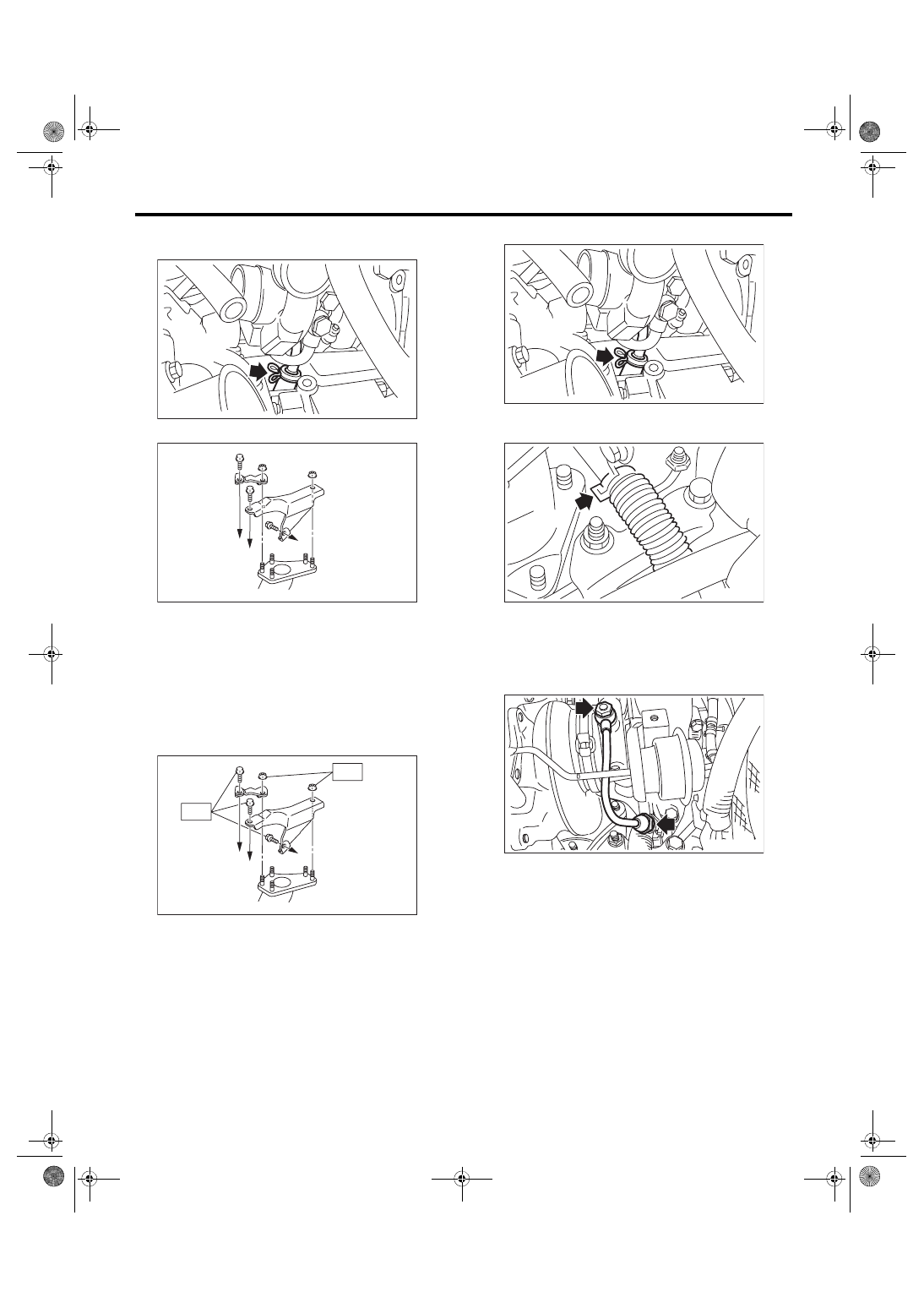
B: INSTALLATION

1) Install the turbocharger stay.
Tightening torque:

T1: 33 N·m (3.4 kgf-m, 24.3 ft-lb)

T2: 42.5 N·m (4.3 kgf-m, 31.3 ft-lb)

2) Connect the oil outlet hose to the oil outlet pipe.

3) Connect the engine coolant hoses to the water

pipe.

4) Temporarily  tighten  the  union  bolts  and  flare

nuts  which  secure  the  oil  inlet  pipe  to  the  turbo-

charger.
NOTE:

Use a new gasket.

(A) To cylinder head RH
(B) To cylinder block RH

(A) To cylinder head RH
(B) To cylinder block RH

IN-02310

IN-02859

(A)

(A)

(B)

T1

IN-02860

(A)

(A)

(B)

T2

IN-02310

IN-02938

IN-02937

IN(w/o STI)-16

Turbocharger

INTAKE (INDUCTION)

5) Tighten the union bolts and flare nuts which se-

cure the oil inlet pipe to the turbocharger.
CAUTION:

In order to prevent damaging the oil pipe on the

cylinder head side, fix the section (a) shown in

the figure when tightening the oil inlet pipe flare

nut, and  avoid the part from rotating together

while tightening the nut.

Tightening torque:

T1: 16 N·m (1.6 kgf-m, 11.8 ft-lb)

T2: 20 N·m (2.0 kgf-m, 14.8 ft-lb)

6) Connect the air control hose (A), and install the

intake duct to the turbocharger.
Tightening torque:

3 N·m (0.3 kgf-m, 2.2 ft-lb)

7) Connect the engine coolant hoses to the coolant

filler tank.

8) Install the joint pipe to turbocharger.
NOTE:

Replace the gasket with a new part.
Tightening torque:

42.5 N·m (4.3 kgf-m, 31.3 ft-lb)

9) Lift up the vehicle.

10) Install  the  center  exhaust  pipe.  <Ref.  to

EX(STI)-9,  INSTALLATION,  Center  Exhaust

Pipe.>

11) Lower the vehicle.

12) Install the intercooler. <Ref. to IN(w/o STI)-12,

INSTALLATION, Intercooler.>

13) Connect the battery ground terminal.

14) Fill  engine  coolant.  <Ref.  to  CO(w/o  STI)-13,

FILLING  OF  ENGINE  COOLANT,  REPLACE-

MENT, Engine Coolant.>

(a)

IN-02955

IN-02939

T1

T2

IN-02940

(A)

IN-02936

IN-02935

IN-00203

IN(w/o STI)-17

Turbocharger

INTAKE (INDUCTION)

C: INSPECTION

1. WASTE GATE ACTUATOR

1) Remove the intercooler. <Ref. to IN(w/o STI)-12,

REMOVAL, Intercooler.>

2) Remove the turbocharger upper cover.

3) Remove the boost hose (B) from the waste gate

actuator (A) of the turbocharger, and connect the

Mighty Vac to the waste gate actuator (A).

4) Pressurize slowly with the Mighty Vac, and mea-

sure the pressure when the control rod stroke (D)

becomes 2 mm (0.08 in). If it is not within the stan-

dard, replace the turbocharger assembly.
CAUTION:

Do not pressurize over 89.9 kPa (0.92 kgf/cm

2

,

13.0  psi)  to  prevent  damaging  the  waste  gate

actuator.
Operating pressure (control rod stroke 2 mm 

(0.08 in)):

Standard

74.7 — 80.8 kPa (0.76 — 0.82 kgf/cm

2

, 10.8 

— 11.7 psi)

5) After  inspection,  install  the  related  parts  in  the

reverse order of removal.
Tightening torque:

7.5 N·m (0.8 kgf-m, 5.5 ft-lb)

2. OTHER INSPECTIONS

1) Check that the turbocharger and pipe have no

deformation, cracks or other damages.

2) Check  that  the  hose  and  intake  duct  have  no

cracks, damage or loose part.

3) Check  that  there  are  no  oil  leakage  or  water

leakage from the pipe attachment section.

(A) Waste gate actuator
(B) Boost hose

(C) Control rod
(D) Control rod stroke

EX-02662

(C)

(B)

(A)

IN-02941

(D)

IN(w/o STI)-18

Air By-pass Valve

INTAKE (INDUCTION)

8. Air By-pass Valve

A: REMOVAL

Disconnect  the  air  by-pass  pipe  (A)  and  vacuum

hose  (B)  from  the  air  by-pass  valve,  and  remove

the air by-pass valve from the intercooler.

B: INSTALLATION

Install in the reverse order of removal.
NOTE:

• Use new O-rings.

• Be careful not to pinch the O-ring.
Tightening torque:

6.5 N·m (0.7 kgf-m, 4.8 ft-lb)

C: INSPECTION

1. AIR BY-PASS VALVE

1) Check that the air by-pass valve has no defor-

mation, cracks or other damages.

2) Connect the Mighty Vac to the nipple (A) of the

air by-pass valve.

3) Using  the  Mighty  Vac,  generate  the  negative

pressure  to  –93.3  kPa  (–0.95  kgf/cm

2

,  –13.5  psi).

Check that the Mighty Vac gauge needle holds 10

seconds without falling by –92.6 kPa (–0.94 kgf/cm

2

,

–13.4 psi).

4) Set a dial gauge to the end of valve rod of the air

by-pass valve.

5) Using  the  Mighty  Vac,  generate  the  negative

pressure, and check the pressure when dial gauge

needle (valve stroke) shows 0.5 mm (0.02 in). If it is

not  within  the  standard,  replace  the  air  by-pass

valve.
Opening pressure (valve stroke 0.5 mm (0.02 

in)):

Standard

–53.3 — –61.3 kPa (–0.54 — –0.63 kgf/cm

2

–7.73 — –8.89 psi)

6) Generate the additional negative pressure from

5), and check the pressure when dial gauge needle

(valve stroke) shows 7.5 mm (0.3 in). If it is not with-

in the standard, replace the air by-pass valve.
Full open pressure (valve stroke 7.5 mm (0.3 

in)):

Standard

–93.4 — –108 kPa (–0.95 — –1.10 kgf/cm

2

–13.5 — –15.7 psi)

2. OTHER INSPECTIONS

Check that the vacuum hose and air by-pass pipe

have no cracks, damage or loose part.

IN-03076

(A)

(B)

IN-02604

(A)

IN-02605


Content   ..  152  153  154  155   ..