Subaru Impreza 3 / Impreza WRX / Impreza WRX STI. Manual - part 153
IN(w/o STI)-11
Intake Duct
INTAKE (INDUCTION)
5. Intake Duct
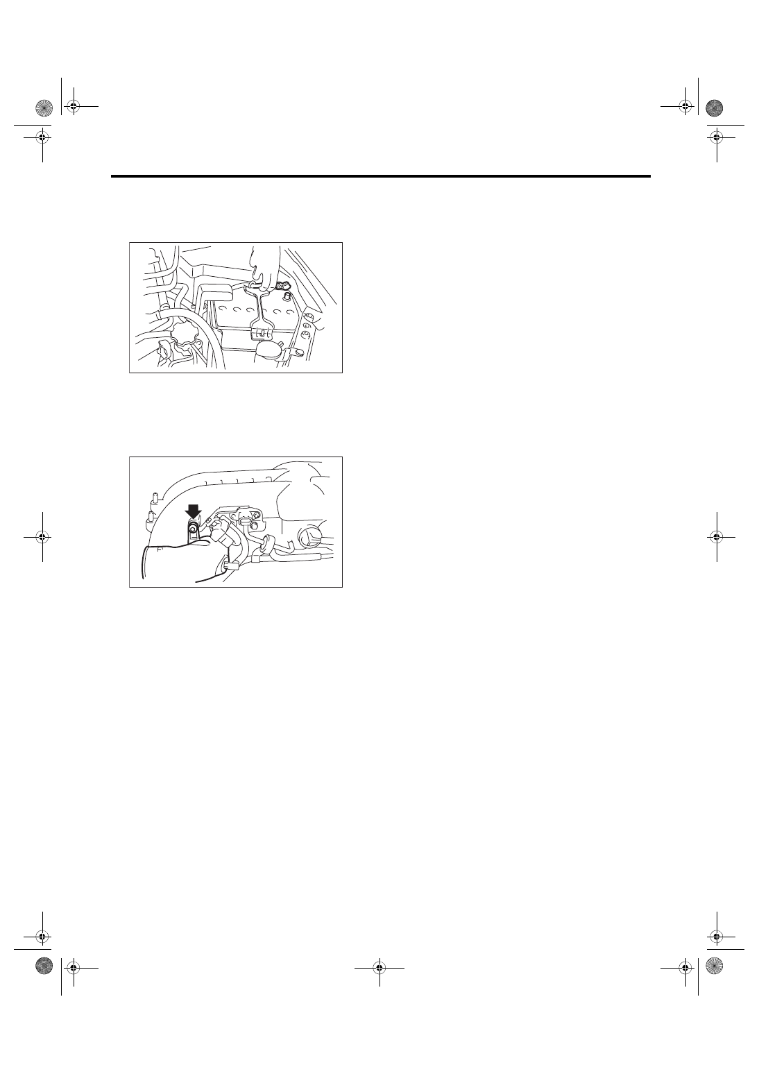
A: REMOVAL
1) Disconnect the ground cable from battery.
2) Remove the intake manifold. <Ref. to FU(w/o
STI)-18, REMOVAL, Intake Manifold.>
3) Remove the sensor, engine harness and fuel
pipe from the intake manifold. <Ref. to FU(w/o
STI)-26, DISASSEMBLY, Intake Manifold.>
4) Remove the intake duct from intake manifold.
B: INSTALLATION
Install in the reverse order of removal.
Tightening torque:
17 N·m (1.7 kgf-m, 12.5 ft-lb)
C: INSPECTION
Check that the intake duct has no deformation,
cracks or other damages.
IN-00203
IN-02505