Subaru Impreza 3 / Impreza WRX / Impreza WRX STI. Manual - part 149
EC(w/o STI)-29
Secondary Air Pump
EMISSION CONTROL (AUX. EMISSION CONTROL DEVICES)
15.Secondary Air Pump
A: REMOVAL
1) Disconnect the ground cable from battery.
2) Remove the clip (A) which holds the harness on
the harness stay and remove the bolt (B) which
holds the secondary air pump on the vehicle.
3) Disconnect the connector (A) and air duct (B)
from secondary air pump and remove the second-
ary air pump.
B: INSTALLATION
Install in the reverse order of removal.
Tightening torque:
19 N·m (1.9 kgf-m, 14.0 ft-lb)
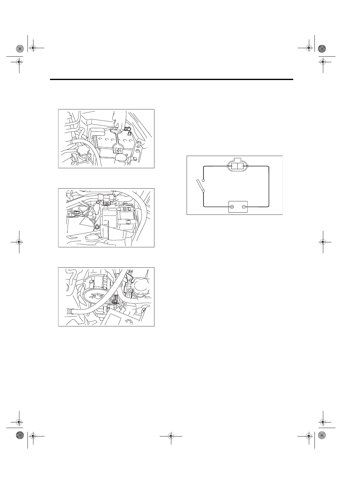
C: INSPECTION
1. SECONDARY AIR PUMP
1) Check that the secondary air pump has no defor-
mation, cracks or other damages.
2) Connect battery positive terminal to the terminal
No. 2 and battery negative terminal to the terminal
No. 1, and inspect the secondary air pump opera-
tion.
CAUTION:
Do not operate the secondary air pump contin-
uously for 80 seconds or more.
2. OTHER INSPECTIONS
Check that the air duct has no cracks, damage or
loose part.
IN-00203
EC-02691
(B)
(A)
EC-02743
(A)
(B)
EC-02427
2 1