Subaru Impreza 3 / Impreza WRX / Impreza WRX STI. Manual - part 146
EC(w/o STI)-17
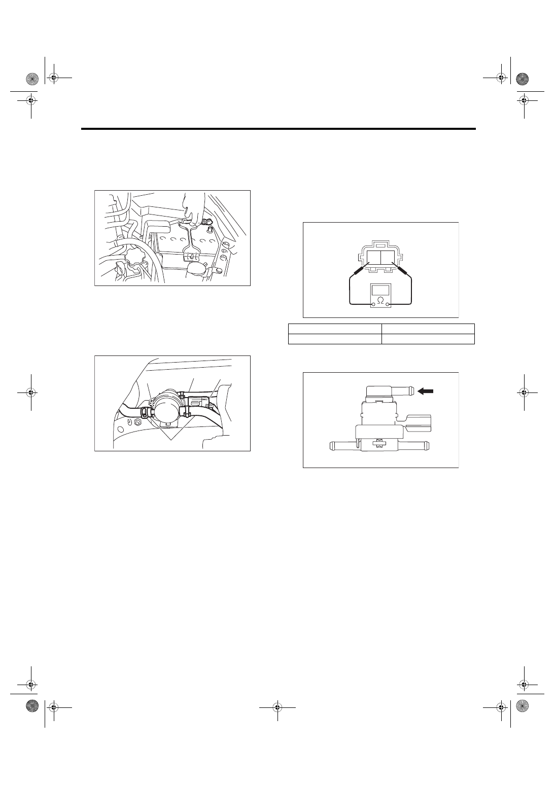
Pressure Control Solenoid Valve Assembly
EMISSION CONTROL (AUX. EMISSION CONTROL DEVICES)
8. Pressure Control Solenoid
Valve Assembly
A: REMOVAL
1) Disconnect the ground cable from battery.
2) Lift up the vehicle.
3) Disconnect the connector (A) and evaporation
hose (B) from the pressure control solenoid valve
assembly.
4) Remove the nut (C) securing the bracket to the
fuel tank and remove the pressure control solenoid
valve assembly.
B: INSTALLATION
Install in the reverse order of removal.
Tightening torque:
7.35 N·m (0.7 kgf-m, 5.4 ft-lb)
C: INSPECTION
1. PRESSURE CONTROL SOLENOID
VALVE ASSEMBLY
1) Check that the pressure control solenoid valve
assembly has no deformation, cracks or other dam-
ages.
2) Check the resistance between the pressure con-
trol solenoid valve assembly terminals.
3) Connect the Mighty Vac to fuel tank side of the
pressure control solenoid valve assembly.
4) Using the Mighty Vac, generate the positive
pressure. Check that the Mighty Vac gauge needle
rises at the pressure (0.55 — 1.55 kPa (0.006 —
0.016 kgf/cm
2
, 0.08 — 0.23 psi)) then lowers.
5) Using the Mighty Vac, generate the vacuum
pressure. Check that the Mighty Vac gauge needle
does not rise.
2. OTHER INSPECTIONS
Check that the evaporation hose has no cracks,
damage or loose part.
IN-00203
EC-03067
(A)
(B)
(B)
(C)
Terminal No.
Standard
1 and 2
20 — 30 Ω
(A) Fuel tank side
(B) Canister side
(C) Atmospheric pressure
EC-02454
2 1
EC-03225
(B)
(A)
(C)