Subaru Impreza 3 / Impreza WRX / Impreza WRX STI. Manual - part 138
FU(w/o STI)-79
Fuel Pump
FUEL INJECTION (FUEL SYSTEMS)
B: INSTALLATION
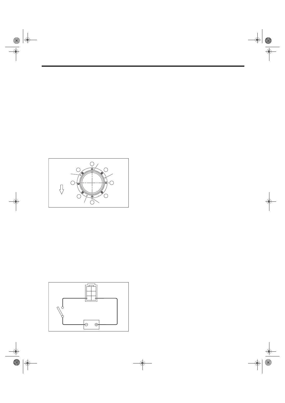
Install in the reverse order of removal while being
careful of the following.
• Make sure the sealing portion is free from fuel or
foreign matter before installation.
• Align protrusion (A) of the gasket to the position
shown in the figure.
• Insert the protrusion (B) of gasket to the fuel
pump upper plate. (3 places)
• Align the protrusion (C) of fuel pump assembly
with the cutout on the fuel pump upper plate.
• Tighten the nuts to the specified torque in the or-
der as shown in the figure.
NOTE:
Use a new gasket.
Tightening torque:
4.4 N·m (0.4 kgf-m, 3.2 ft-lb)
C: INSPECTION
1) Check that the fuel pump has no deformation,
cracks or other damages.
2) Connect the battery positive terminal to terminal
No. 5 and the battery ground terminal to terminal
No. 6, and inspect the fuel pump operation.
WARNING:
• Wipe off fuel completely.
• Keep the battery as far apart from fuel pump
as possible.
• Do not run the fuel pump for a long time un-
der non-load condition.
(a) Front side of vehicle
FU-04532
1
2
3
4
5
6
7
8
(C)
(B)
(B)
(B)
(A)
(a)
FU-04110
2 1
4 3
6 5