Subaru Impreza 3 / Impreza WRX / Impreza WRX STI. Manual - part 137
FU(w/o STI)-75
Fuel Filler Pipe
FUEL INJECTION (FUEL SYSTEMS)
25.Fuel Filler Pipe
A: REMOVAL
WARNING:
Place “NO OPEN FLAMES” signs near the
working area.
CAUTION:
Be careful not to spill fuel.
1) Release the fuel pressure. <Ref. to FU(w/o STI)-
65, RELEASING OF FUEL PRESSURE, PROCE-
2) Drain fuel. <Ref. to FU(w/o STI)-65, DRAINING
FUEL (WITH SUBARU SELECT MONITOR),
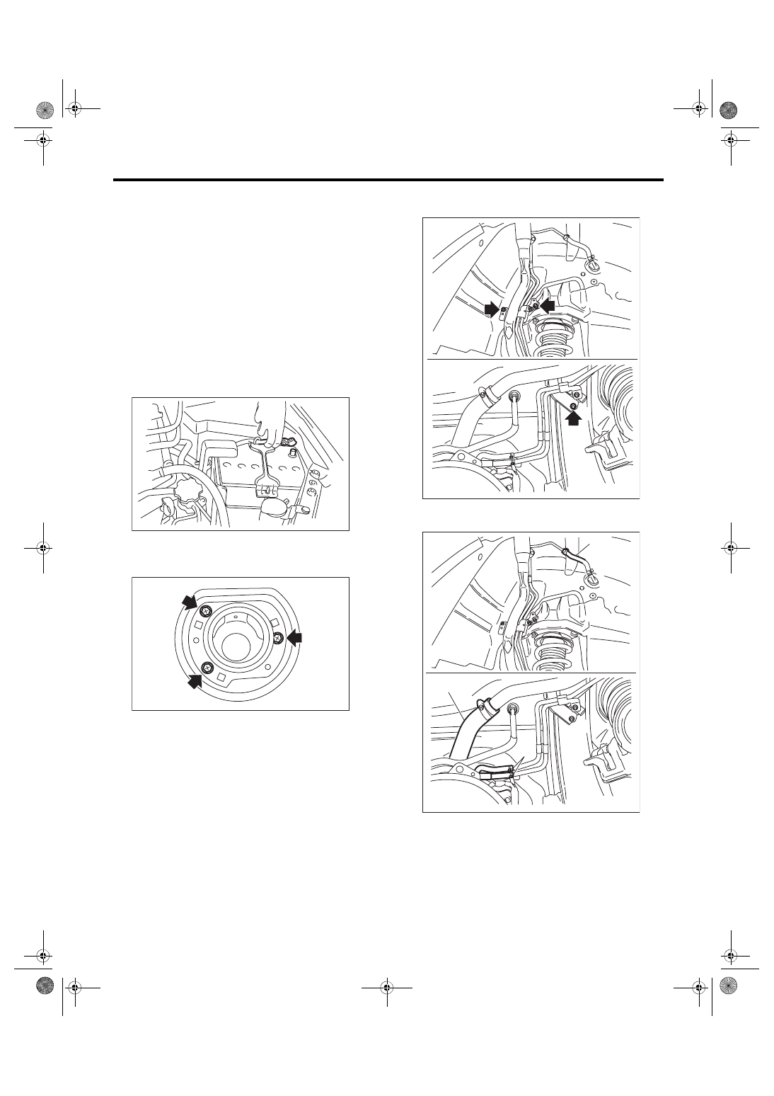
3) Disconnect the ground cable from battery.
4) Open the fuel filler lid, and remove the filler cap.
5) Remove the screws which secure the fuel filler
ring, and then remove the fuel filler ring.
6) Remove the rear wheel RH.
7) Lift up the vehicle.
8) Remove the rear mud guard RH. <Ref. to EI-30,
REAR MUD GUARD, REMOVAL, Mud Guard.>
9) Remove the rear sub frame. <Ref. to RS-17, RE-
10) Remove the bolts and nuts which secure fuel
filler pipe assembly onto the vehicle body.
11) Disconnect the fuel filler hose (A) and evapora-
tion hose (B) from the fuel filler pipe assembly.
12) Remove the fuel filler pipe assembly from the
underside of the vehicle.
IN-00203
FU-03835
FU-03426
(B)
FU-05755
(A)
(B)