Subaru Impreza 3 / Impreza WRX / Impreza WRX STI. Manual - part 108
SP(STI)-2
General Description
SPEED CONTROL SYSTEMS
1. General Description
A: SPECIFICATION
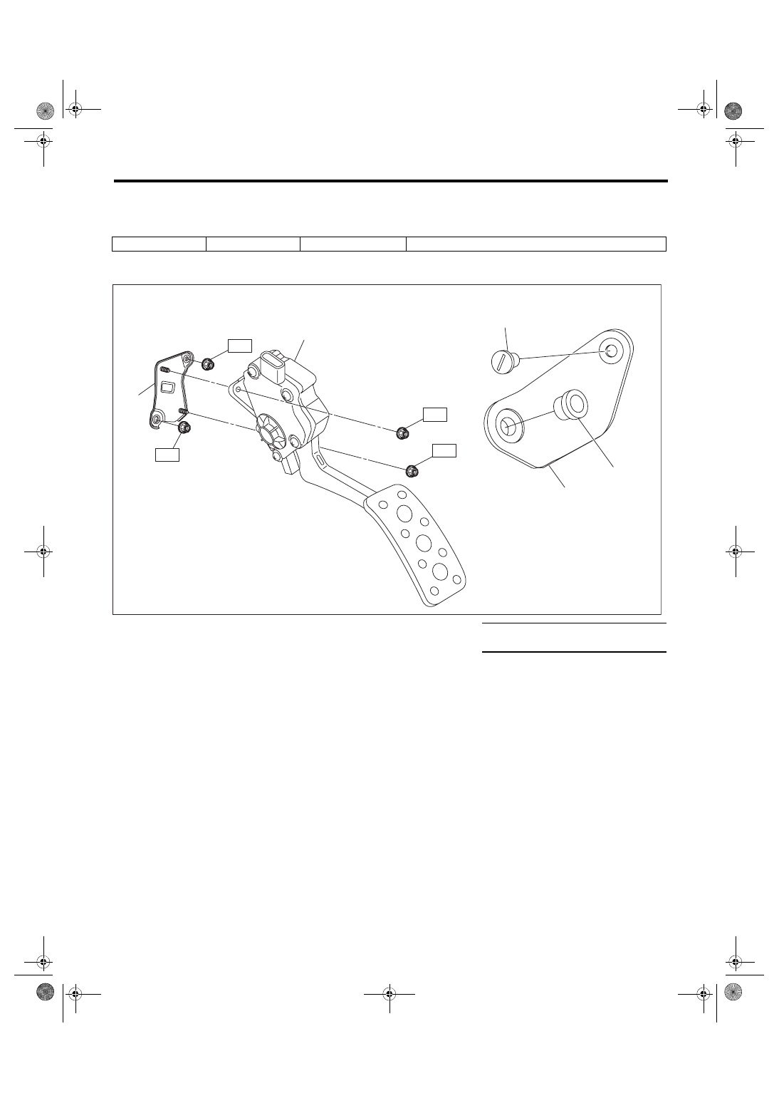
B: COMPONENT
Accelerator pedal
Stroke
At pedal pad
50 — 59 mm (1.97 — 2.32 in)
(1)
Accelerator pedal ASSY
(4)
Accelerator stopper
Tightening torque: N·m (kgf-m, ft-lb)
(2)
Clip
(5)
Accelerator pedal bracket
T: 18 (1.8, 13.3)
(3)
Accelerator plate
SP-02066
T
T
(1)
(5)
(4)
T
T
(3)
(2)