Subaru Impreza 3 / Impreza WRX / Impreza WRX STI. Manual - part 103
LU(STI)-14
Oil Pump
LUBRICATION
B: INSTALLATION
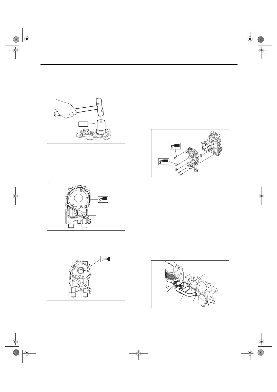
1) Using the ST, install the front oil seal.
ST 499587100
OIL SEAL INSTALLER
NOTE:
Use a new front oil seal.
2) Apply liquid gasket to the mating surfaces of oil
pump.
NOTE:
Install within 5 min. after applying liquid gasket.
Liquid gasket:
THREE BOND 1217G (Part No. K0877Y0100)
or equivalent
3) Apply a coat of engine oil to the inside of front oil
seal.
4) Install the oil pump to cylinder block.
CAUTION:
• Be careful not to damage the front oil seal
during installation.
• Make sure the front oil seal lip is not folded.
NOTE:
• Align the flat surface of oil pump’s inner rotor with
that of crankshaft before installation.
• Use new O-rings.
• Do not forget to install O-rings.
5) Apply liquid gasket to the three bolts thread
shown in figure. (when reusing bolts)
Liquid gasket:
THREE BOND 1324 (Part No. 004403042) or
equivalent
Tightening torque:
6.4 N·m (0.7 kgf-m, 4.7 ft-lb)
6) Install the crank sprocket. <Ref. to ME(STI)-60,
INSTALLATION, Crank Sprocket.> <Ref. to ME(w/
o STI)-58, INSTALLATION, Crank Sprocket.>
7) Install the water pump. <Ref. to CO(STI)-15, IN-
STALLATION, Water Pump.> <Ref. to CO(w/o
STI)-15, INSTALLATION, Water Pump.>
8) Install the crankshaft position sensor. <Ref. to
FU(STI)-35, INSTALLATION, Crankshaft Position
Sensor.> <Ref. to FU(w/o STI)-35, INSTALLA-
TION, Crankshaft Position Sensor.>
9) Lift up the vehicle.
10) Install oil cooler pipe (A) and hose (C). (Model
with oil cooler)
11) Install the oil cooler pipe (A) to oil pump using
the bolts (B). (Model with oil cooler)
Tightening torque:
6.4 N·m (0.7 kgf-m, 4.7 ft-lb)
12) Lower the vehicle.
13) Install the radiator. <Ref. to CO(STI)-20, IN-
STALLATION, Radiator.> <Ref. to CO(w/o STI)-
(A) O-ring
LU-00021
ST
ME-00165
(A)
ME-00312
ME-04946
LU-02396
(B)
(C)
(C)
(A)