Subaru Impreza 3 / Impreza WRX / Impreza WRX STI. Manual - part 66
 

  Index      Subaru     Subaru Impreza 3 / Impreza WRX / Impreza WRX STI - service repair manual 2008-2014 year


Search            


Content   ..  64  65  66  67   ..


Subaru Impreza 3 / Impreza WRX / Impreza WRX STI. Manual - part 66


ME(STI)-26

Valve Clearance

MECHANICAL

8. Valve Clearance

A: INSPECTION

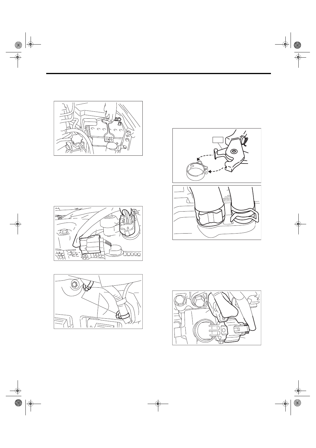
1) Disconnect the ground cable from battery.

2) Remove  the  engine  from  vehicle.  <Ref.  to

ME(STI)-30, REMOVAL, Engine Assembly.>

3) Remove  the  timing  belt  cover  RH.  <Ref.  to

ME(STI)-49, REMOVAL, Timing Belt Cover.>

4) When inspecting #1 and #3 cylinders

(1) Disconnect  the  connector  (A)  from  the  ex-

haust  camshaft  position  sensor  RH  and  the

connector (B) form the exhaust oil flow control

solenoid valve RH.

(2) Remove the clip (A) which hold the engine

harness to the rocker cover RH.

(3) Remove the ignition coil. <Ref. to IG(STI)-7,

REMOVAL, Ignition Coil.>

(4) Disconnect PCV hose (A) and vacuum hose

(B) from the rocker cover RH.

NOTE:

Pinch the clamp of the PCV hose (A) by fitting the

cut out in the ST with the protrusion on the clamp as

shown in the figure, and unlock the clamp.

ST 18353AA000 CLAMP PLIERS

(5) Remove the rocker cover RH.

5) When inspecting #2 and #4 cylinders

(1) Remove  the  secondary  air  pump.  <Ref.  to

EC(STI)-27,  REMOVAL,  Secondary  Air

Pump.>

(2) Disconnect  the  connector  (A)  from  the  ex-

haust camshaft position sensor LH and the con-

nector  (B)  form  the  exhaust  oil  flow  control

solenoid valve LH.

IN-00203

ME-05009

(B)

(A)

ME-05041

(A)

ME-04374

ST

ME-05755

(A)

(B)

ME-05010

(B)

(A)

ME(STI)-27

Valve Clearance

MECHANICAL

(3) Remove the air duct B (B) from the rocker

cover LH and the air duct A (A).

(4) Remove the ignition coil. <Ref. to IG(STI)-7,

REMOVAL, Ignition Coil.>

(5) Disconnect PCV hose (A) and vacuum hose

(B) from the rocker cover LH.

NOTE:

Pinch the clamp of the PCV hose (A) by fitting the

cut out in the ST with the protrusion on the clamp as

shown in the figure, and unlock the clamp.

ST 18353AA000 CLAMP PLIERS

(6) Remove the rocker cover LH.

6) Turn the crank pulley clockwise until the round

mark and arrow mark on the cam sprocket are set

to position shown in the figure.
NOTE:

Turn the crank pulley using a socket wrench.

• Measurement of clearance of #1 cylinder intake

valve and #3 cylinder exhaust valve

• Measurement  of  clearance  of  #2  cylinder  ex-

haust valve and #3 cylinder intake valve

• Measurement of clearance of #2 cylinder intake

valve and #4 cylinder exhaust valve

• Measurement  of  clearance  of  #1  cylinder  ex-

haust valve and #4 cylinder intake valve

ME-04953

(B)

(A)

ME-04374

ST

ME-05757

(A)

(B)

ME-04091

ME-03172

ME-03173

ME-03174

ME(STI)-28

Valve Clearance

MECHANICAL

7) Measure the clearance of intake valve and ex-

haust valve using thickness gauge (A).
NOTE:

• Insert a thickness  gauge in  a  direction as hori-

zontal as possible with respect to the valve lifter.

• Lift  up  the  vehicle,  and  then  measure  the  ex-

haust valve clearances.

• If the measured value is not within the inspection

value, take notes of the value in order to adjust the

valve clearance later on.
Valve clearance (inspection value):

Intake

0.20

+0.04


–0.06

 mm (0.0079

+0.0016


–0.0024

 in)

Exhaust

0.35

±

0.05 mm (0.0138

±

0.0020 in)

8) If necessary, adjust the valve clearance. <Ref. to

ME(STI)-29, ADJUSTMENT, Valve Clearance.>

9) After  inspection,  install  the  related  parts  in  the

reverse order of removal.
NOTE:

• Refer  to  “Camshaft”  when  installing  the  rocker

cover. <Ref. to ME(STI)-64, INSTALLATION, Cam-

shaft.>

• Use a new clamp for the PCV hose (A), fit the cut

out in the ST with the protrusion on the clamp as

shown in the figure, and lock the clamp.

ST 18353AA000 CLAMP PLIERS

Tightening torque:

6.4 N·m (0.7 kgf-m, 4.7 ft-lb)

ME-04958

(A)

ME-04374

ST

ME-05976

(A)

(A)

ME-04954

ME(STI)-29

Valve Clearance

MECHANICAL

B: ADJUSTMENT

1) Measure  all  the  valve  clearances.  <Ref.  to

ME(STI)-26, INSPECTION, Valve Clearance.>
NOTE:

Record  the  measured  value  of  each  valve  clear-

ance.

2) Remove the camshaft. <Ref. to ME(STI)-61, RE-

MOVAL, Camshaft.>

3) Remove the valve lifter.

4) Measure  the  thickness  of  valve  lifter  using  mi-

crometer.

5) Select a valve lifter of suitable thickness using

the measured valve clearance and valve lifter thick-

ness, and install it.
NOTE:

Use a new valve lifter.

6) Install  the  camshaft.  <Ref.  to  ME(STI)-64,  IN-

STALLATION, Camshaft.>

7) Install  the  cam  sprocket.  <Ref.  to  ME(STI)-59,

INSTALLATION, Cam Sprocket.>

8) Install the timing belt. <Ref. to ME(STI)-53, TIM-

ING BELT, INSTALLATION, Timing Belt.>

9) Measure all valves for valve clearance again at

this time. If the valve clearance is not within the ad-

justment  value,  repeat  the  procedure  over  again

from step 2).
Valve clearance (adjustment value):

Intake

0.20

+0.01


–0.03

 mm (0.0079

+0.0004


–0.0012

 in)

Exhaust

0.35

±

0.02 mm (0.0138

±

0.0008 in)

10) After adjustment, install the related parts in the

reverse order of removal.

Unit: mm (in)

Intake valve: S = (V + T) – 0.19 (0.0075)
Exhaust valve: S = (V + T) – 0.35 (0.0138)
S: Valve lifter thickness required
V: Measured valve clearance
T: Valve lifter thickness to be used

ME-00024

ME-00025


Content   ..  64  65  66  67   ..