Subaru Impreza 3 / Impreza WRX / Impreza WRX STI. Manual - part 49
EC(STI)-10
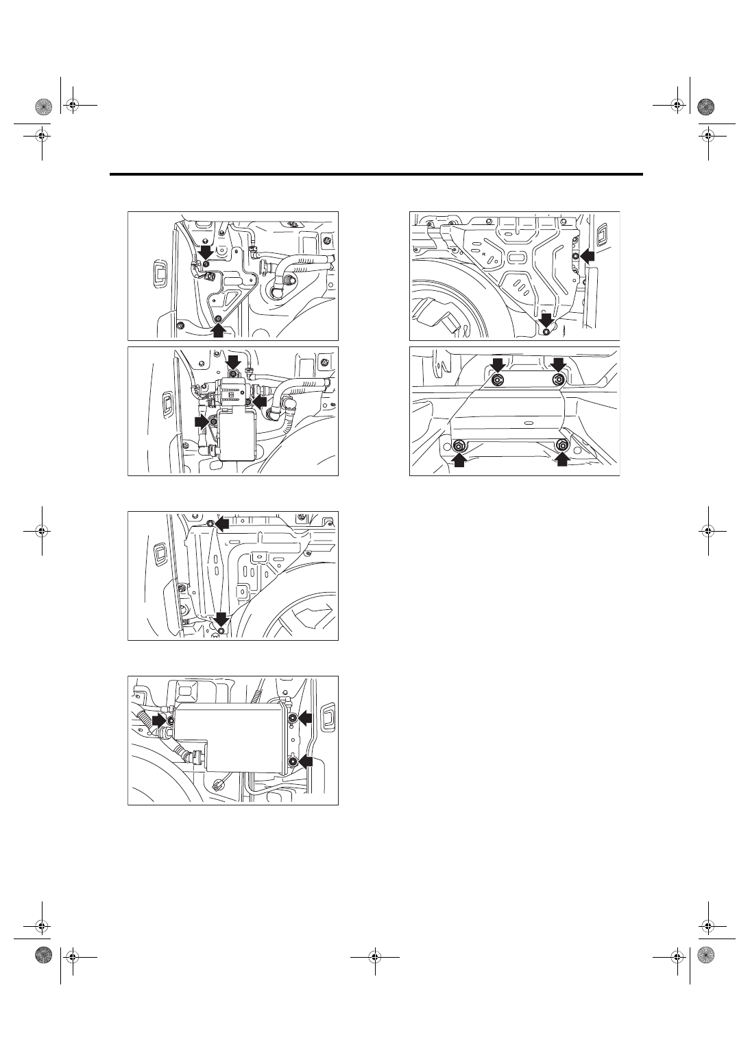
Canister
EMISSION CONTROL (AUX. EMISSION CONTROL DEVICES)
Tightening torque:
7.5 N·m (0.8 kgf-m, 5.5 ft-lb)
Tightening torque:
18 N·m (1.8 kgf-m, 13.3 ft-lb)
Tightening torque:
8 N·m (0.8 kgf-m, 5.9 ft-lb)
Tightening torque:
18 N·m (1.8 kgf-m, 13.3 ft-lb)
C: INSPECTION
1) Check that the canister and leak check valve as-
sembly have no deformation, cracks or other dam-
ages.
2) Check that the tube has no cracks, damage or
loose part.
EC-02982
EC-02983
EC-02984
EC-02985
EC-02986
EC-02987