Subaru Impreza 3 / Impreza WRX / Impreza WRX STI. Manual - part 40
 

  Index      Subaru     Subaru Impreza 3 / Impreza WRX / Impreza WRX STI - service repair manual 2008-2014 year


Search            


Content   ..  38  39  40  41   ..


Subaru Impreza 3 / Impreza WRX / Impreza WRX STI. Manual - part 40


FU(STI)-72

Fuel Tank

FUEL INJECTION (FUEL SYSTEMS)

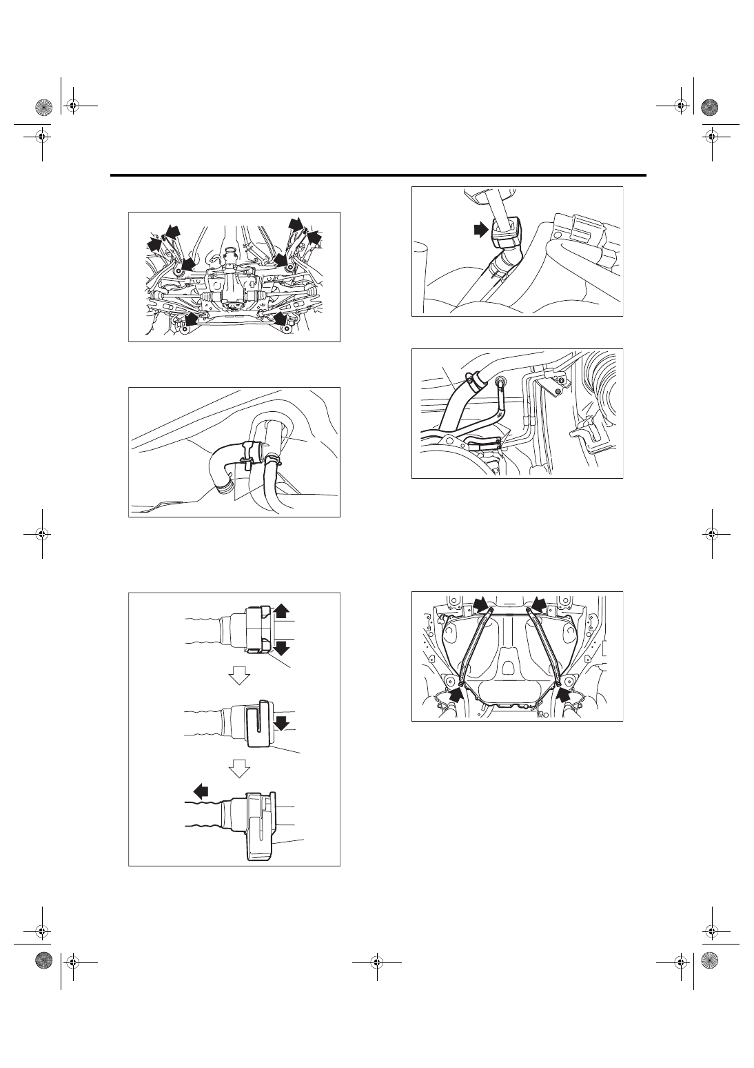
(3) Remove  the  bolts  which  secure  the  rear

suspension assembly to the body.

(4) Remove the rear suspension assembly.

21) Disconnect the evaporation hose (B) from hose

connector (A).

22) Disconnect the quick connector of the evapora-

tion hose from the evaporation pipe.
NOTE:

Disconnect the quick connector as shown in the fig-

ure.

23) Disconnect the fuel filler hose (A) and evapora-

tion hose (B).

24) Support the fuel tank with a transmission jack,

remove  the  fuel  tank  band,  and  remove  the  fuel

tank from the vehicle.
WARNING:

• A helper is required to perform this work.

• Fuel  may  remain  in  the  fuel  tank.  This  will

cause the left and right sides to be unbalanced.

Be careful not to drop the fuel tank.

(a) Retainer

FU-06588

FU-05719

(A)

(B)

EC-02281

(a)

(a)

(a)

FU-04627

FU-05720

(A)

(B)

FU-06555

FU(STI)-73

Fuel Tank

FUEL INJECTION (FUEL SYSTEMS)

B: INSTALLATION

1) Support the fuel tank with a  transmission jack,

set the fuel tank and the fuel tank band in place,

and  temporarily  tighten  the  bolts  of  the  fuel  tank

band.
WARNING:

A helper is required to perform this work.

2) Securely insert the fuel filler hose (A) and evap-

oration  hose  (B)  until  the  hose  end  contacts  the

spool, then attach the clamp or clip as shown in the

figure.
Tightening torque:

2.5 N·m (0.3 kgf-m, 1.8 ft-lb)

3) Connect the quick connector of the evaporation

hose to the evaporation pipe.
CAUTION:

• Check that there is no damage or dust on the

quick  connector.  If  necessary,  clean  the  seal

surface of the pipe.

• When  connecting  the  quick  connector,  se-

curely insert the pipe all the way before locking

the retainer.

• When it is difficult to lock the retainer, make

sure that the pipe is securely inserted.

• Make sure that the quick connector is secure-

ly connected.

(1) Hose
(2) Clamp or clip
(3) Spool
(4) Pipe

FU-06555

FU-05720

(A)

(B)

FU-05646

(1)

(2)

(4)

L

L/2

(3)

(a) Retainer

EC-02295

(a)

(a)

(a)

FU-04627

FU(STI)-74

Fuel Tank

FUEL INJECTION (FUEL SYSTEMS)

4) Connect the evaporation hose (B) to hose con-

nector (A).

5) Tighten the bolts of the fuel tank band in the or-

der shown in the figure.
Tightening torque:

33 N·m (3.4 kgf-m, 24.3 ft-lb)

6) Install the rear suspension assembly.
WARNING:

A helper is required to perform this work.

(1) Support the rear differential with the trans-

mission jack.

(2) Support the rear suspension assembly and

install  the  rear  suspension  assembly  to  the

body.

Tightening torque:

T1: 70 N·m (7.1 kgf-m, 51.6 ft-lb)

T2: 145 N·m (14.8 kgf-m, 106.9 ft-lb)

(3) Install  the  rear  shock  absorber  to  the  rear

suspension arm.

NOTE:

Use a new self-locking nut.
Tightening torque:

80 N·m (8.2 kgf-m, 59.0 ft-lb)

7) Connect  the  connectors  to  oil  temperature

switch (A) and ground (B), and secure the harness

with clips (C).

8) Install  the  parking  brake  cable  clamp  to  the

body.
Tightening torque:

18 N·m (1.8 kgf-m, 13.3 ft-lb)

FU-05719

(A)

(B)

FU-03596

3

1

2

4

FU-06589

T1

T1

T2

FU-03359

FU-04571

(A)

(B)

(C)

FU-03278

FU(STI)-75

Fuel Tank

FUEL INJECTION (FUEL SYSTEMS)

9) Connect  the  connector  to  the  rear  ABS  wheel

speed sensor.
NOTE:

Prevent the harness identification (line) from being

twisted when installing. (RH: White line, LH: Yellow

line)

10) Install the heat shield cover.
Tightening torque:

18 N·m (1.8 kgf-m, 13.3 ft-lb)

11) Install the fuel tank protector.
NOTE:

Use a new self-locking nut.
Tightening torque:

Nut: 9 N·m (0.9 kgf-m, 6.6 ft-lb)

Bolt: 18 N·m (1.8 kgf-m, 13.3 ft-lb)

12) Install the propeller shaft. <Ref. to DS-12, IN-

STALLATION, Propeller Shaft.>

13) Install the rear exhaust pipe and muffler. <Ref.

to  EX(STI)-13,  INSTALLATION,  Rear  Exhaust

Pipe.> <Ref. to EX(STI)-15, INSTALLATION, Muf-

fler.>

14) Lower the vehicle.

15) Connect the parking brake cable to the parking

brake  assembly.  <Ref.  to  PB-7,  INSTALLATION,

Parking Brake Assembly (Rear Disc Brake).>

16) Install the rear disc brake assembly.
Tightening torque:

65 N·m (6.6 kgf-m, 47.9 ft-lb)

17) Install the rear brake hose bracket to the rear

housing.
Tightening torque:

33 N·m (3.4 kgf-m, 24.3 ft-lb)

18) Attach the rear ABS wheel speed sensor to the

rear housing.
NOTE:

Prevent the harness identification (line) from being

twisted when installing. (RH: White line, LH: Yellow

line)
Tightening torque:

7.5 N·m (0.8 kgf-m, 5.5 ft-lb)

19) Install the rear wheels.
Tightening torque:

100 N·m (10.2 kgf-m, 73.8 ft-lb)

20) Connect  the  quick  connector  of  fuel  delivery

tube (A) and fuel return tube (B). <Ref. to FU(STI)-

96,  INSTALLATION,  Fuel  Delivery,  Return  and

Evaporation Lines.>
NOTE:

When connecting, be careful not to reverse the de-

livery side and return side.

FU-03277

FU-04388

FU-04088

FU-03357

FU-05675

(B)

(A)


Content   ..  38  39  40  41   ..