Subaru Legacy (2005 year). Manual - part 927
 

  Index      Subaru     Subaru Legacy - service repair manual 2005 year


Search            


Content   ..  925  926  927  928   ..


Subaru Legacy (2005 year). Manual - part 927


LI-5

LIGHTING SYSTEM

Rear Fog Light System

4. Rear Fog Light System

A: WIRING DIAGRAM

1. REAR FOG LIGHT

<Ref. to WI-250, WIRING DIAGRAM, Rear Fog
Light System.>

B: INSPECTION

1. REAR FOG LIGHT SWITCH

Measure the rear fog light switch resistance be-
tween terminals. <Ref. to LI-10, INSPECTION,
Combination Switch (Light).>

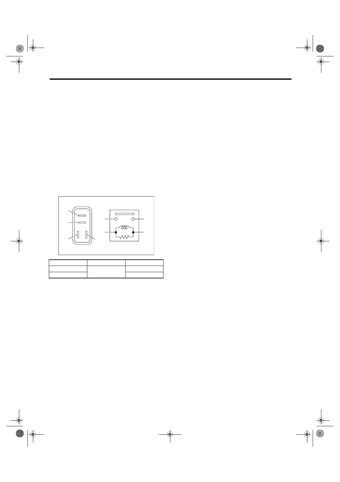
2. REAR FOG LIGHT RELAY

Measure the resistance between rear fog light relay
terminals while connecting terminal No. 4 to battery
positive terminal and No. 3 to battery ground termi-
nal.

Current

Terminal No.

Standard

Flow

1 and 2

Less than 1 

No flow

More than 1 M

LI-00001

(1)

(2)

(1)

(4)

(2)

(3)

(3)

(4)

LI-6

LIGHTING SYSTEM

Turn Signal Light and Hazard Light System

5. Turn Signal Light and Hazard 

Light System

A: WIRING DIAGRAM

1. TURN SIGNAL LIGHT AND HAZARD 
LIGHT SYSTEM

<Ref. to WI-263, WIRING DIAGRAM, Turn Signal
Light and Hazard Light System.>

B: INSPECTION

1. TURN SIGNAL SWITCH

<Ref. to LI-10, INSPECTION, Combination Switch
(Light).>

2. HAZARD SWITCH

Measure the resistance between hazard switch ter-
minals.

3. TURN SIGNAL LIGHT AND HAZARD 
LIGHT MODULE

Connect the battery and turn signal light bulb to the
module. The module is properly functioning if it
blinks when power is supplied to the circuit.

Switch position

Terminal No.

Standard

OFF

2 and 3

More than 1 M

ON

Less than 1 

LI-00261

4

3

2

1

LI-00262

3

2 1

8 7 6 5 4

LI-7

LIGHTING SYSTEM

Back-up Light System

6. Back-up Light System

A: WIRING DIAGRAM

1. BACK-UP LIGHT

<Ref. to WI-252, WIRING DIAGRAM, Back-up
Light System.>

B: INSPECTION

1. BACK-UP LIGHT SWITCH (MT MODEL)

Measure the resistance between back-up light
switch terminals.

2. INHIBITOR SWITCH (4AT MODEL)

Measure the resistance between inhibitor switch
terminals.

3. BACK-UP LIGHT RELAY (5AT MODEL)

Measure the resistance between back-up light re-
lay terminals when connecting terminal No. 4 to
battery positive terminal and terminal No. 3 to bat-
tery ground terminal.

NOTE:
Check other than back-up light relay. <Ref. to 4AT-
51, INSPECTION, Inhibitor Switch.>

Switch position

Terminal No.

Standard

When shift lever is 

set in reverse 

position

1 and 2

Less than 1 

Other positions

More than 1 M

Switch position

Terminal No.

Standard

When the selec-
tor lever is in “R” 

range

1 and 2

Less than 1 

Other positions

More than 1 M

LI-00263

2

1

9

LI-00005

4 3 2 1

5

6

7

8

10

11

12

Current

Terminal No.

Standard

Flow

1 and 2

Less than 1 

No flow

More than 1 M

LI-00001

(1)

(2)

(1)

(4)

(2)

(3)

(3)

(4)

LI-8

LIGHTING SYSTEM

Stop Light System

7. Stop Light System

A: WIRING DIAGRAM

1. STOP LIGHT

<Ref. to WI-254, WIRING DIAGRAM, Stop Light
System.>

B: INSPECTION

1. STOP LIGHT SWITCH

Measure the resistance between stop light switch
terminals.

(1) Model without cruise control

(2) Model with cruise control

Switch position

Terminal No.

Standard

When brake pedal 

is depressed

Model without 

cruise control: 1 

and 2

Less than 1 

When brake pedal 

is released

Model with cruise 

control: 2 and 3

More than 1 M

LI-00265

3

4

1

2

1

2

(1)

(2)


Content   ..  925  926  927  928   ..