Subaru Legacy (2005 year). Manual - part 800
 

  Index      Subaru     Subaru Legacy - service repair manual 2005 year


Search            


Content   ..  798  799  800  801   ..


Subaru Legacy (2005 year). Manual - part 800


VDC(diag)-65

VEHICLE DYNAMICS CONTROL (VDC) (DIAGNOSTICS)

Diagnostic Procedure with Diagnostic Trouble Code (DTC)

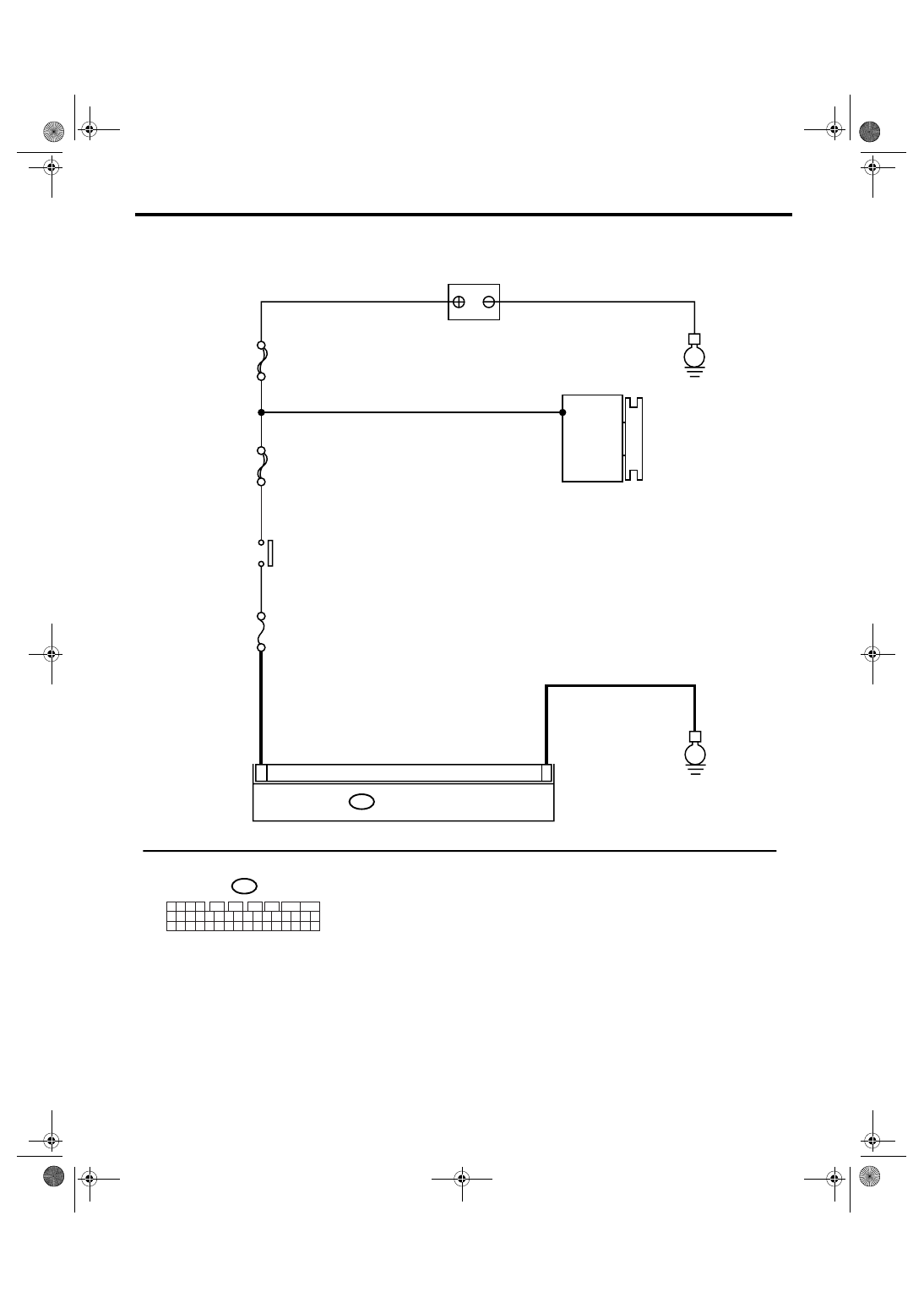
WIRING DIAGRAM:

VDC00309

MAIN SBF

SBF-6

No.33

B310

B310

E

E

6

14

VDCCM & H/U

1 2 3 4

11 12 13 14
27 28 29 30

15 16 17 18
31 32 33 34

19 20 21 22
35 36 37 38

23 24 25 26
39 40 41 42

5

6

7

8

9

10

BATTERY

GENERATOR

IGNITION
SWITCH

VDC(diag)-66

VEHICLE DYNAMICS CONTROL (VDC) (DIAGNOSTICS)

Diagnostic Procedure with Diagnostic Trouble Code (DTC)

AB:DTC C0042 ABS WHEEL SPEED SENSOR POWER MALFUNCTION

NOTE:
For the diagnostic procedure, refer to DTC C0042 “POWER VOLTAGE MALFUNCTION”. <Ref. to VDC(di-
ag)-64, DTC C0042 POWER VOLTAGE MALFUNCTION, Diagnostic Procedure with Diagnostic Trouble
Code (DTC).>

Step

Check

Yes

No

1

CHECK GENERATOR.
1) Start the engine.
2) Run the engine at idle after warming up.
3) Measure the voltage between generator B 
terminal and chassis ground.

Terminals

Generator B terminal (+) — Chassis 
ground (

):

Is the voltage 10 — 15 V?

Go to step 2.

Repair the genera-
tor. <Ref. to 
SC(H4SO 2.0)-14, 
Generator.>

2

CHECK BATTERY TERMINAL.
Turn the ignition switch to OFF.

Are the positive and negative 
battery terminals clamped 
tightly?

Go to step 3.

Tighten the termi-
nal.

3

CHECK INPUT VOLTAGE FOR VDCCM&H/
U.
1) Disconnect the connector from VDCCM&H/
U.
2) Run the engine at idle.
3) Operate the devices such as headlights, air 
conditioner, defogger, etc. which produce 
much electrical loading.
4) Measure the voltage between VDCCM&H/
U connector and chassis ground.

Connector & terminal

(B310) No. 14 (+) — Chassis ground (

):

Is the voltage 10 — 15 V?

Go to step 4.

Repair the power 
supply circuit.

4

CHECK GROUND CIRCUIT OF VDCCM&H/U.
1) Turn the ignition switch to OFF.
2) Measure the resistance between 
VDCCM&H/U connector and chassis ground.

Connector & terminal

(B310) No. 6 — Chassis ground:

Is the resistance less than 0.5 
Ω?

Go to step 5.

Repair the 
VDCCM&H/U 
ground harness.

5

CHECK POOR CONTACT IN CONNECTORS. Is there poor contact in con-

nector between generator, bat-
tery and VDCCM&H/U?

Repair the con-
nector.

Go to step 6.

6

CHECK VDCCM&H/U.
1) Connect all the connectors.
2) Perform the clear memory mode.
3) Perform the inspection mode.
4) Read the DTC.

Is the same DTC displayed?

Replace the 
VDCCM&H/U. 
<Ref. to VDC-7, 
VDC Control Mod-
ule and Hydraulic 
Control Unit 
(VDCCM&H/U).>

Go to step 7.

7

CHECK OTHER DTC DETECTION.

Is any other DTC displayed?

Perform the diag-
nosis according to 
DTC. <Ref. to 
VDC(diag)-38, List 
of Diagnostic Trou-
ble Code (DTC).>

Temporary poor 
contact occurs.

VDC(diag)-67

VEHICLE DYNAMICS CONTROL (VDC) (DIAGNOSTICS)

Diagnostic Procedure with Diagnostic Trouble Code (DTC)

AC:DTC C0044 AT COMMUNICATION

DTC DETECTING CONDITION:
No CAN signal from TCM.
TROUBLE SYMPTOM:
• ABS does not operate.
• VDC does not operate.

Step

Check

Yes

No

1

CHECK LAN SYSTEM.
Perform the diagnosis for LAN system. <Ref. to 
LAN(diag)-24, OPERATION, Read Diagnostic 
Trouble Code (DTC).>

Is there any fault in LAN sys-
tem?

Perform the diag-
nosis according to 
DTC for LAN sys-
tem.

Go to step 2.

2

CHECK POOR CONTACT IN CONNECTORS. Is there poor contact in TCM 

connector?

Repair the con-
nector.

Go to step 3.

3

CHECK TCM.

Is the TCM normal?

Go to step 4.

Replace the TCM. 
<Ref. to 4AT-66, 
Transmission Con-
trol Module 
(TCM).> <Ref. to 
5AT-61, Transmis-
sion Control Mod-
ule (TCM).>

4

CHECK VDCCM&H/U.
1) Connect all the connectors.
2) Perform the clear memory mode.
3) Perform the inspection mode.
4) Read the DTC.

Is the same DTC displayed?

Replace the 
VDCCM&H/U.

Go to step 5.

5

CHECK OTHER DTC DETECTION.

Is any other DTC displayed?

Perform the diag-
nosis according to 
DTC.

It results from a 
temporary noise 
interference.

VDC(diag)-68

VEHICLE DYNAMICS CONTROL (VDC) (DIAGNOSTICS)

Diagnostic Procedure with Diagnostic Trouble Code (DTC)

AD:DTC C0045 DIFFERENT VDC CONTROL MODULE SPECIFICATION

DTC DETECTING CONDITION:
Different control module specification
TROUBLE SYMPTOM:
• ABS does not operate.
• VDC does not operate.

Step

Check

Yes

No

1

CHECK VDCCM&H/U SPECIFICATION.
Check the identification mark of VDCCM&H/U.

Identification mark of VDCCM&H/U

OUTBACK 3.0 R: G2
Wagon model 2.5 i: G3
Wagon model 3.0 R (AT model): G4
Sedan model 2.5 i: G9
Sedan model 3.0 R (AT model): GA
OUTBACK 2.5 i: GE
Wagon model 3.0 R (MT model): GH
Sedan model 3.0 R (MT model): GJ

Is the identification mark of 
VDCCM&H/U the same as 
vehicle specification?

Go to step 2.

Replace the 
VDCCM&H/U. 
<Ref. to VDC-7, 
VDC Control Mod-
ule and Hydraulic 
Control Unit 
(VDCCM&H/U).>

2

CHECK TCM SPECIFICATION.
Check the TCM specification.

Is the specification of TCM 
same as vehicle specification?

Go to step 3.

Replace the TCM. 
<Ref. to 4AT-66, 
Transmission Con-
trol Module 
(TCM).> <Ref. to 
5AT-61, Transmis-
sion Control Mod-
ule (TCM).>

3

CHECK AT SYSTEM.
1) Start the engine.
2) Check the DTC in AT system.

Is DTC of AT system dis-
played?

Repair the AT sys-
tem.

Go to step 4.

4

CHECK ECM SPECIFICATION.
Check the ECM specification.

Is the specification of ECM 
same as vehicle specification?

Go to step 5.

Replace the ECM. 
<Ref. to FU(H4SO 
2.0)-34, Engine 
Control Module 
(ECM).> <Ref. to 
FU(H4DOTC)-34, 
Engine Control 
Module (ECM).> 
<Ref. to 
FU(H6DO)-34, 
Engine Control 
Module (ECM).>

5

CHECK VDCCM&H/U.
1) Connect all the connectors.
2) Perform the clear memory mode.
3) Perform the inspection mode.
4) Read the DTC.

Is the same DTC displayed?

Replace the 
VDCCM&H/U.

Go to step 6.

6

CHECK OTHER DTC DETECTION.

Is any other DTC displayed?

Perform the diag-
nosis according to 
DTC.

It results from a 
temporary noise 
interference.


Content   ..  798  799  800  801   ..