Subaru Legacy (2005 year). Manual - part 713


  Index      Subaru     Subaru Legacy - service repair manual 2005 year


Search            


Content   ..  711  712  713  714   ..


Subaru Legacy (2005 year). Manual - part 713


FS-23

FRONT SUSPENSION

Front Strut

7) Pull the piston rod fully upward, and install the
spring seat.

NOTE:
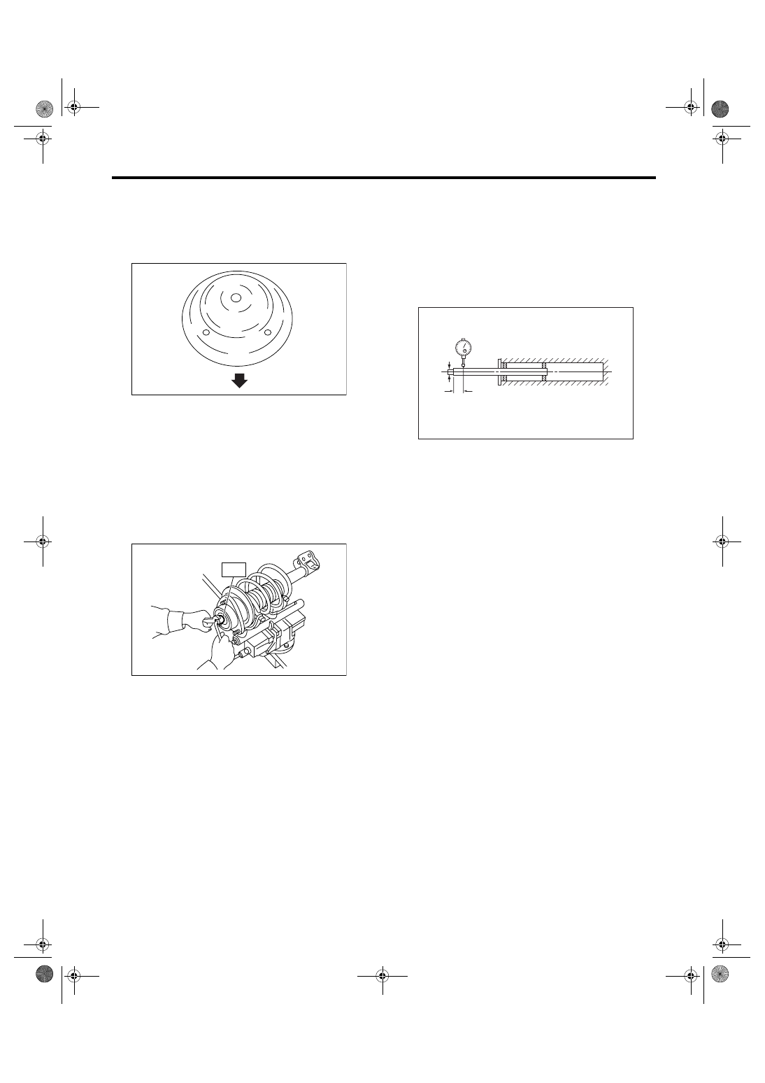
Ensure the upper spring seat is positioned as
shown in the figure.

8) Install the strut mount to piston rod, and tempo-
rarily tighten a new self-locking nut.
9) Using a hexagon wrench to prevent strut rod
from turning, tighten the new self-locking nut with
ST.
ST

20399AG000 STRUT MOUNT SOCKET

Tightening torque:

70 N

m (7.1 kgf-m, 51.6 ft-lb)

10) Loosen the coil spring carefully.

E: INSPECTION

Check the removed part for wear, damage and
cracks, and then repair or replace it if defective.

1. DAMPER STRUT

1) Check for oil leaks.
2) Move the piston rod up and down to check that it
operates smoothly without any hitch.

3) Piston rod play
• Measure the play as follows:
Fix the outer shell and fully extend the rod. Set a
dial gauge at the end of rod L [10 mm (0.39 in)], and
then read the dial gauge indication P

1

 while apply-

ing a force of W [20 N (2 kgf, 4 lbf)] to threaded end.
Apply a force of 20 N (2 kgf, 4 lbf) in the opposite di-
rection of “W”, and then read the dial gauge indica-
tion P

2

.

Play limit (P

1

 + P

2

):

0.8 mm (0.031 in)

If the play exceeds limit, replace the strut.

2. STRUT MOUNT

Check the rubber part for deformation, cracks or
deterioration, and then replace it with a new one if
defective.

3. DUST COVER

If any cracks or damage are found, replace it with a
new one.

4. COIL SPRING

If a permanent strain is found, replaced it with a
new one.

5. HELPER

Replace it with a new one if cracked or damaged.

F: DISPOSAL

1. EXCEPT BILSTEIN STRUT

CAUTION:
• Before handling struts, be sure to wear gog-
gles to protect eyes from gas, oil and cutting
powder.
• Do not disassemble the strut damper or place
into a fire.
• Drill a hole into struts in case of discarding
struts filled with gas.
1) Place the strut on a level surface with the piston
rod fully expanded.

(1) Outside of body

FS-00128

(1)

FS-00041

ST

FS-00046

W

L

FS-24

FRONT SUSPENSION

Front Strut

2) Using a 2 to 3 mm (0.08 to 0.12 in) dia. drill,
make holes in areas shown in the figure.

2. BILSTEIN STRUT

CAUTION:
• Before handling struts filled with gas, be sure
to wear goggles to protect eyes from gas, oil
and cutting powder.
• Do not disassemble the strut damper or place
into a fire.
• Drill a hole into struts in case of discarding
struts filled with gas.
1) Place the gas-filled strut on a level surface with
the dumping tube fully extended.
2) Using a 2 to 3 mm (0.08 to 0.12 in) dia. drill,
make a hole at the position (1) first, and then make
a hole at the position (2).

(1) 40 mm (1.57 in)

(1) 20 mm (0.78 in)

(2) 10 mm (0.39 in)

(3) Strut

(4) Damping tube

FS-00047

(1)

FS-00096

(1)

(4)

(2)

(3)

FS-25

FRONT SUSPENSION

Front Crossmember

8. Front Crossmember

A: REMOVAL

1) Lift-up the vehicle, and then remove the front
wheels.
2) Remove the front exhaust pipe.
3) Remove the front crossmember support plate.
<Ref. to FS-14, REMOVAL, Front Crossmember
Support Plate.>
4) Remove the front stabilizer. <Ref. to FS-15, RE-
MOVAL, Front Stabilizer.>
5) Disconnect the tie-rod end from housing.
6) Remove the front arm. <Ref. to FS-18, REMOV-
AL, Front Arm.> 
7) Remove the nuts attaching the engine mount
cushion rubber to crossmember. 

8) Remove the steering universal joint.
9) Disconnect the power steering hose from steer-
ing gearbox.
10) Lift the engine approx. 10 mm (0.39 in) using
chain block. 
11) Support the crossmember with a jack, remove
the bolts securing crossmember to body, and then
gradually lower the crossmember with steering
gearbox as a unit.

CAUTION:
When removing the crossmember downward, 
be careful that the tie-rod end does not interfere 
with drive shaft boot.

B: INSTALLATION

1) Install in the reverse order of removal.

NOTE:
• Use a new bolt and self-locking nut. For not reus-
able part, refer to “COMPONENT”. <Ref. to FS-4,
COMPONENT, General Description.>
• Always tighten the bushing in the state that
wheels are in full contact with the ground and the
vehicle is curb weight.

Tightening torque:

Crossmember to body

95 N

m (9.7 kgf-m, 70.1 ft-lb)

Engine mounting to crossmember

85 N

m (8.7 kgf-m, 62.7 ft-lb)

Front arm-to-Crossmember

95 N

m (9.7 kgf-m, 70.1 ft-lb)

Front arm-to-Support plate

110 N

m (11.2 kgf-m, 81.1 ft-lb)

Support plate body

150 N

m (15.3 kgf-m, 110.6 ft-lb)

Tie-rod end to housing

27 N

m (2.75 kgf-m, 19.9 ft-lb)

Retighten the castle nut further within 60

° until the

hole in ball stud is aligned with a slot in castle nut
after tightening in specified torque.

Tightening torque:

Universal Joint

24 N

m (2.4 kgf-m, 17.4 ft-lb)

Stabilizer bracket

25 N

m (2.5 kgf-m, 18.4 ft-lb)

Stabilizer link

45 N

m (4.6 kgf-m, 33.2 ft-lb)

Power steering hose-to-Steering gearbox

15 N

m (1.5 kgf-m, 10.8 ft-lb) 

2) Purge air from the power steering system.
3) Inspect the wheel alignment and adjust if neces-
sary.

C: INSPECTION

Check the crossmember for wear, damage or
cracks, and then repair or replace if defective.

FS-00118

FS-00119

FS-26

FRONT SUSPENSION

General Diagnostic Table

9. General Diagnostic Table

A: INSPECTION

1. IMPROPER VEHICLE POSTURE OR IMPROPER WHEEL ARCH HEIGHT

2. POOR RIDE COMFORT

• Large rebound shock
• Rocking of the vehicle continues too long after running over bump and hump.
• Large shock in bumping

3. NOISE

Possible cause

Corrective action

(1) Permanent distortion or breakage of coil spring

Replace.

(2) Rough operation of damper strut or shock absorber

Replace.

(3) Installation of wrong strut or shock absorber

Replace with proper parts.

(4) Installation of wrong coil spring

Replace with proper parts.

Possible cause

Corrective action

(1) Breakage of coil spring

Replace.

(2) Overinflation pressure of tire

Adjust.

(3) Improper wheel arch height

Adjust or replace the coil springs with new ones.

(4) Fault in operation of damper strut or shock absorber

Replace.

(5) Damage or deformation of strut mount or shock absorber mount

Replace.

(6) Unsuitability of maximum or minimum length of damper strut or shock 
absorber

Replace with proper parts.

(7) Deformation or loss of bushing

Replace.

(8) Deformation or damage of helper in strut assembly or shock absorber

Replace.

(9) Oil leakage of damper strut or shock absorber

Replace.

Possible cause

Corrective action

(1) Wear or damage of damper strut or shock absorber component parts

Replace.

(2) Loosening of suspension link installing bolt

Tighten to the specified torque.

(3) Deformation or loss of bushing

Replace.

(4) Unsuitability of maximum or minimum length of damper strut or shock 
absorber

Replace with proper parts.

(5) Breakage of coil spring

Replace.

(6) Wear or damage of ball joint

Replace.

(7) Deformation of stabilizer clamp

Replace.


Content   ..  711  712  713  714   ..