Subaru Legacy (2005 year). Manual - part 711


  Index      Subaru     Subaru Legacy - service repair manual 2005 year


Search            


Content   ..  709  710  711  712   ..


Subaru Legacy (2005 year). Manual - part 711


FS-15

FRONT SUSPENSION

Front Stabilizer

4. Front Stabilizer

A: REMOVAL

1) Lift-up the vehicle, and then remove the front
wheels.
2) Remove the front under cover. <Ref. to EI-26,
REMOVAL, Front Under Cover.>
3) Remove the front crossmember support plate.
<Ref. to FS-14, REMOVAL, Front Crossmember
Support Plate.>
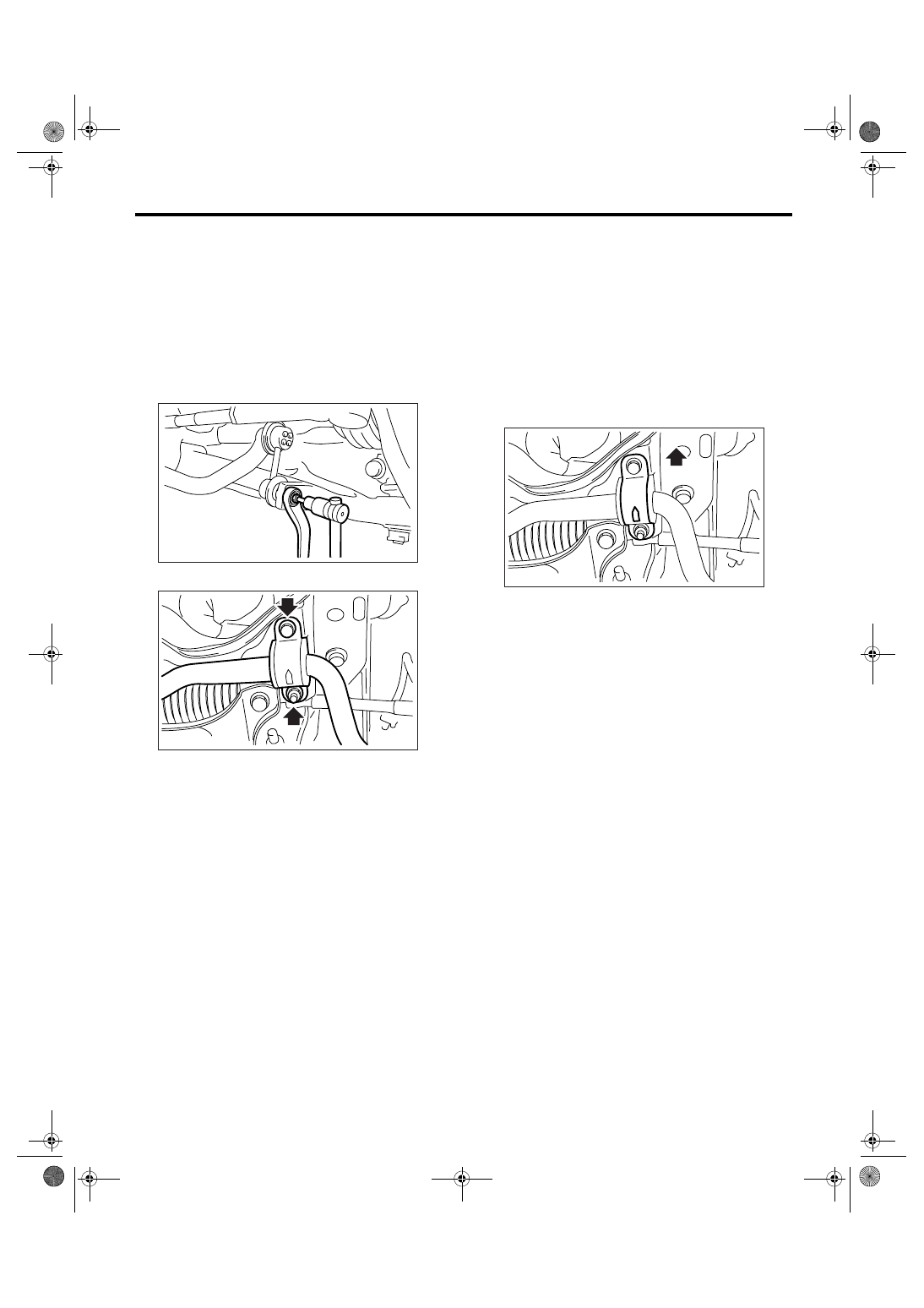
4) Remove the stabilizer link.

5) Remove the stabilizer bracket.

B: INSTALLATION

Install in the reverse order of removal.

NOTE:
• Use a new self-locking nut.
• Ensure the stabilizer bushing and stabilizer have
the same identification colors.
• Install the stabilizer bushing (front crossmember
side) while aligning it with the paint mark on stabi-
lizer.
• Stabilizer bracket has an orientation, so install it
with the arrow mark faced to the front side of vehi-
cle.

Tightening torque:

Stabilizer link

45 N

m (4.6 kgf-m, 33.2 ft-lb)

Stabilizer bracket

25 N

m (2.5 kgf-m, 18.4 ft-lb)

C: INSPECTION

1) Check the bushing for crack, fatigue or damage.
2) Check the stabilizer link for damage.

FS-00117

FS-00114

(1) Front side of vehicle

FS-00116

(1)

FS-16

FRONT SUSPENSION

Front Ball Joint

5. Front Ball Joint

A: REMOVAL

1) Lift-up the vehicle, and remove the front wheels.
2) Remove the both sides of stabilizer bracket.

3) Pull out the pin from ball stud, remove the castle
nut, and extract the ball stud from front arm.
4) Remove the bolt installing ball joint to housing.

5) Extract the ball joint from housing.

B: INSTALLATION

1) Insert the ball joint into housing.

Tightening torque (Bolt):

50 N

m (5.1 kgf-m, 36.9 ft-lb)

CAUTION:
Do not apply grease to the tapered portion of 
ball stud.
2) Install the ball joint into front arm.

Tightening torque (Castle nut):

39 N

m (4.0 kgf-m, 28.8 ft-lb)

3) Retighten the castle nut further within 60

° until

the hole in ball stud is aligned with a slot in castle
nut. Then, insert a new cotter pin and bend it
around castle nut.

4) Install the stabilizer bracket.

NOTE:
Stabilizer bracket has an orientation, so install it
with the arrow mark faced to the front side of vehi-
cle.

Tightening torque:

25 N

m (2.5 kgf-m, 18.4 ft-lb)

5) Install the front wheels.

C: INSPECTION

1) Measure the play of ball joint by the following
procedures. Replace with a new one when the play
exceeds specification.

(1) With 686 N (70 kgf, 154 lbf) loaded in direc-
tion shown in the figure, measure the dimension

2

1

.

(2) With 686 N (70 kgf, 154 lbf) loaded in direc-
tion shown in the figure, measure the dimension

2

2

.

FS-00114

FS-00115

(1) Front side of vehicle

FS-00116

(1)

FS-00035

FS-00036

FS-17

FRONT SUSPENSION

Front Ball Joint

(3) Determine the plays from the following cal-
culation formula. S = 

2

2


− 2

1

(4) Replace with a new one when the play ex-
ceeds specification.

FRONT BALL JOINT

Specification for replacement S:

Less than 0.3 mm (0.012 in)

2) When the play is within specification, visually
check the dust cover.
3) Remove the ball joint and cover, check them for
wear, damage or cracks, and then replace them if
any defective part is found.
4) If the dust cover is damaged, replace with a new
ball joint.

FS-18

FRONT SUSPENSION

Front Arm

6. Front Arm

A: REMOVAL

1) Lift-up the vehicle, and then remove the front
wheels.
2) Remove the front crossmember support plate.
<Ref. to FS-14, REMOVAL, Front Crossmember
Support Plate.>
3) Remove the front stabilizer. <Ref. to FS-15, RE-
MOVAL, Front Stabilizer.>
4) Remove the ball joint of front arm.

5) Remove the nut securing the front arm to cross-
member. (Do not remove the bolt.)

6) Remove the front arm support plate.

7) Remove the bolt securing front arm to cross-
member and extract the front arm from crossmem-
ber.

8) To remove the stud bolt, use the ST.
ST

20299AG020 STUD BOLT SOCKET

CAUTION:
Do not remove the stud bolt without necessity. 
Always replace the parts with new ones when 
removed.

B: INSTALLATION

1) Using the ST, install the stud bolt.
ST

20299AG020 STUD BOLT SOCKET

Tightening torque:

110 N

m (11.2 kgf-m, 81.1 ft-lb)

2) Using new bolts and self-locking nuts, temporari-
ly tighten the front arm to crossmember.
3) Secure the front arm to body, and then install the
support plate with new bolts and self-locking nuts.

Tightening torque:

Support plate-to-Front arm

110 N

m (11.2 kgf-m, 81.1 ft-lb)

Support plate to Body

150 N

m (15.3 kgf-m, 110.6 ft-lb) 

4) Install the ball joint into housing.

Tightening torque:

50 N

m (5.1 kgf-m, 36.9 ft-lb)

5) Install the stabilizer. <Ref. to FS-15, INSTALLA-
TION, Front Stabilizer.>
6) Lower the vehicle from the lift, and tighten the
bolt which secures front arm to crossmember at the
state that wheels are in full contact with the ground
and the vehicle is curb weight.

Tightening torque:

95 N

m (9.7 kgf-m, 70.1 ft-lb)

NOTE:
Inspect the wheel alignment and adjust if neces-
sary.

FS-00106

FS-00107

FS-00108

(1) Vehicle body

(2) Stud bolt

FS-00109

(2)

(1)

ST


Content   ..  709  710  711  712   ..