Subaru Legacy (2005 year). Manual - part 687


  Index      Subaru     Subaru Legacy - service repair manual 2005 year


Search            


Content   ..  685  686  687  688   ..


Subaru Legacy (2005 year). Manual - part 687


6MT-95

MANUAL TRANSMISSION AND DIFFERENTIAL

Reverse Idler Gear

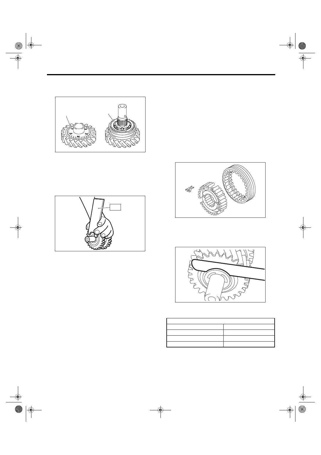
12) Align the protrusion portion of reverse synchro
cone with reverse idler gear hole, then install the
reverse idler gear.

13) Install the washer with groove facing to reverse
idler gear.
14) Using the ST, install the snap ring.
ST

18672AA000

GUIDE CLIP

15) Inspect and adjust the clearance between snap
ring and washer. <Ref. to 6MT-95, INSPECTION,
Reverse Idler Gear.>
16) Install the spring pin.

NOTE:
Use a new spring pin.

E: INSPECTION

Disassembled parts should be washed with un-
leaded gasoline first and then inspected carefully.
1) Bearing
Replace the bearings in the following cases.
• When there are wear, rust and damage on the
bearing.
• When bearing that fails to turn smoothly or
makes noise when turned.
• When bearings have other defects.
2) Bushing (each gear)
Replace the bushing in following cases.
• When the sliding surface is damaged or abnor-
mally worn.

3) Gear
Replace the gear in the following cases.
• When the gear teeth surfaces are broken or ex-
cessively worn.
• When the parts that contact the baulk ring is
damaged.
• When the inner surface of gear is damaged.
4) Baulk ring, synchro cone
Replace the baulk ring and synchro cone in the fol-
lowing case.
• When there are wear, rust and damage on the
baulk ring.
5) Shifting insert key
Replace the shifting insert key if deformed, exces-
sively worn or defective in any way.

6) Inspect the clearance between snap ring and
washer.

Tip clearance specification:

0.1 — 0.3 mm (0.0039 — 0.0118 in)

Select the snap ring from the following table if
clearance is out of specification.

Inspect the clearance again after replacing snap
ring.

(A) Protrusion portion of reverse synchro cone

(B) Reverse idler gear hole

(A)

(B)

MT-00637

MT-00638

ST

Snap ring

Part No.

Thickness   mm (in)

031319000

1.50 (0.059)

805019030

1.60 (0.062)

805019010

1.72 (0.068)

MT-00581

MT-00639

6MT-96

MANUAL TRANSMISSION AND DIFFERENTIAL

Drive Pinion Shaft Assembly

22.Drive Pinion Shaft Assembly

A: REMOVAL

1) Remove the manual transmission assembly
from vehicle. <Ref. to 6MT-34, REMOVAL, Manual
Transmission Assembly.>
2) Prepare the transmission for overhaul. <Ref. to
6MT-40, Preparation for Overhaul.>
3) Remove the oil pipe, neutral position switch,
back-up light switch and harness. <Ref. to 6MT-42,
REMOVAL, Oil Pipe.> <Ref. to 6MT-45, REMOV-
AL, Neutral Position Switch.> <Ref. to 6MT-43, RE-
MOVAL, Back-up Light Switch.>
4) Remove the extension case. <Ref. to 6MT-47,
REMOVAL, Extension Case.>
5) Remove the transfer driven gear. <Ref. to 6MT-
58, REMOVAL, Transfer Driven Gear.>
6) Remove the center differential. <Ref. to 6MT-60,
REMOVAL, Center Differential.>
7) Remove the oil pump. <Ref. to 6MT-61, RE-
MOVAL, Oil Pump.>
8) Remove the transmission case. <Ref. to 6MT-
64, REMOVAL, Transmission Case.>
9) Remove each gear assembly. <Ref. to 6MT-69,
REMOVAL, Main Shaft Assembly.>
10) Remove the drive pinion shaft assembly.

B: INSTALLATION

1) Completely remove the remaining gasket on
drive plate and clutch housing.
2) Apply liquid gasket to the clutch housing.

Liquid gasket:

THREE BOND 1215 (Part No. 004403007)

3) Install each gear assembly. <Ref. to 6MT-70, IN-
STALLATION, Main Shaft Assembly.>
4) Install the transmission case. <Ref. to 6MT-65,
INSTALLATION, Transmission Case.>
5) Install the oil pump. <Ref. to 6MT-62, INSTAL-
LATION, Oil Pump.>
6) Install the center differential. <Ref. to 6MT-60,
INSTALLATION, Center Differential.>
7) Install the transfer driven gear. <Ref. to 6MT-58,
INSTALLATION, Transfer Driven Gear.>
8) Install the extension case. <Ref. to 6MT-47, IN-
STALLATION, Extension Case.>
9) Install the oil pipe, neutral position switch, back-
up light switch and harness. <Ref. to 6MT-42, IN-
STALLATION, Oil Pipe.> <Ref. to 6MT-45, IN-
STALLATION, Neutral Position Switch.> <Ref. to
6MT-43, INSTALLATION, Back-up Light Switch.>
10) Install the manual transmission assembly into
vehicle. <Ref. to 6MT-36, INSTALLATION, Manual
Transmission Assembly.>

C: DISASSEMBLY

NOTE:
When replacing the drive pinion shaft and hypoid
driven gear, replace them as a set.
1) Remove the pipe and oil chamber.

2) Remove the drive pinion shaft and shim from
adapter plate.

3) Secure the ST on workbench.
ST

18664AA000

BASE

4) Unlock the caulking of lock nut.

MT-00640

MT-00532

(A) Pipe

(B) Oil chamber

(A)

(B)

MT-00641

MT-00642

6MT-97

MANUAL TRANSMISSION AND DIFFERENTIAL

Drive Pinion Shaft Assembly

5) Install the ST3 to lock nut, then set drive pinion
shaft to ST1 and ST2. Remove the lock nut and
washer.
ST1

18667AA000 HOLDER

ST2

18664AA000 BASE

ST3

18621AA000 ADAPTER WRENCH

6) Using the ST, remove the taper roller bearing as-
sembly.
ST

18723AA000

REMOVER

D: ASSEMBLY

1) Using the ST, measure dimension A of drive pin-
ion.

NOTE:
Refer to dimension A for selection of drive pinion
shim.
ST

499575500

GAUGE

2) Install the inner bearing inner race to drive pinion
shaft using ST and press.
ST

18723AA000

REMOVER

CAUTION:
Do not apply pressure in excess of 40 kN (4.0 
ton, 4.4 US ton, 3.9 Imp ton).

3) Install the retainer and outer bearing inner race
to drive pinion shaft using ST and press.
ST

18723AA000

REMOVER

NOTE:
Press to the point where bearing is turned smoothly
without slack.

4) Install the washer and lock nut.

NOTE:
Use a new lock nut.
5) Set the ST to drive pinion, then tighten the lock
nut.
ST1

18667AA000 HOLDER

ST2

18664AA000 BASE

ST3

18621AA000 ADAPTER WRENCH

ST4

18852AA000 TORQUE WRENCH

MT-00643

ST2

ST3

ST1

MT-00644

ST

A

MT-00645

ST

(A) Retainer

MT-00646

ST

MT-00647

(A)

ST

6MT-98

MANUAL TRANSMISSION AND DIFFERENTIAL

Drive Pinion Shaft Assembly

Tightening torque:

265 N

m (27.0 kgf-m, 195 ft-lb)

NOTE:
If torque wrench except ST4 is used, calculate the
following calculation formula, then tighten the lock
nut.
Tighten with the ST and torque wrench straight-
lined.
T = L1 / (0.1 + L1) 

× 285

6) Measure the starting torque. <Ref. to 6MT-99,
INSPECTION, Drive Pinion Shaft Assembly.>
7) Using the ST, caulk the lock nut at two points at
dimension A of 37

±0.5 mm (1.46±0.02 in).

ST

18670AA000

PUNCH

NOTE:
Do not damage the caulking portion of lock nut.

8) Using the ST, measure dimension B of the drive
pinion.
ST

499575500

GAUGE

9) Calculate the following calculation formula, then
select one or two pieces of drive pinion shim from
the table below.
6.5

±0.0625 mm − (B − A) [0.26±0.0025 in − (B − A)]

NOTE:
A: Measured value from step 1)
B: Measured value from step 8)

T

N

⋅m (kgf-m, ft-lb) Setting value of torque 

wrench

L1

m (in) Torque wrench length

0.1 m (3.94 in)

ST length

285 N

⋅m (29.0 kgf-m, 210 ft-lb) Tightening torque of lock 

nut:

(A) 0.1 m (3.94 in)

MT-00648

ST2

ST4

ST3

ST1

(A)

L1

MT-00614

Drive pinion shim

Part No.

Thickness mm (in)

32295AA270

0.15 (0.0059)

32295AA280

0.175 (0.0069)

32295AA290

0.20 (0.0079)

32295AA300

0.225 (0.0089)

32295AA310

0.25 (0.0098)

32295AA320

0.275 (0.0108)

MT-00649

A

ST

MT-00650

B

ST


Content   ..  685  686  687  688   ..