Subaru Legacy (2005 year). Manual - part 672
6MT-35
MANUAL TRANSMISSION AND DIFFERENTIAL
Manual Transmission Assembly
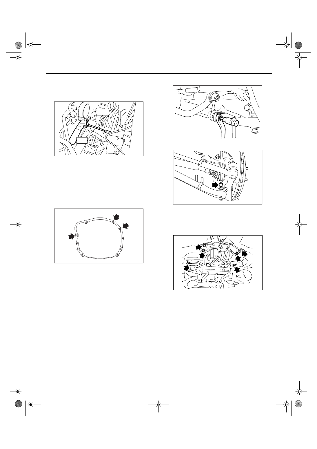
14) Set the ST.
ST1
41099AA010 ENGINE SUPPORT BRACK-
ET
ST2
41099AA020 ENGINE SUPPORT
15) Remove the clutch release shaft.
(1) Remove the plug with hexagon wrench.
(2) Install a 6 mm (0.24 in) bolt to the release
shaft, then pull out the release shaft.
(3) Lift up the release fork, and then remove it
from the release bearing claw. Pull release fork
to the engine side and set it free.
16) Remove the bolts which hold upper side of
transmission to engine.
17) Remove the front exhaust pipe, rear exhaust
pipe and muffler. <Ref. to EX(H6DO)-4, REMOV-
AL, Front Exhaust Pipe.> <Ref. to EX(H6DO)-7,
REMOVAL, Rear Exhaust Pipe.> <Ref. to
EX(H6DO)-9, REMOVAL, Muffler.>
CAUTION:
When removing the exhaust pipes, be careful
each exhaust pipe does not drop out.
18) Remove the heat shield cover.
19) Remove the propeller shaft. <Ref. to DS-10,
REMOVAL, Propeller Shaft.>
20) Remove the front stabilizer link.
21) Remove the ball joint of front arm from housing.
22) Remove the front drive shaft. <Ref. to DS-22,
REMOVAL, Front Drive Shaft.>
23) Set the transmission jack under the transmis-
sion, then remove the front crossmember and rear
crossmember.
MT-01269
ST2
ST1
MT-00466
FS-00117
FS-00106
MT-01264