Subaru Legacy (2005 year). Manual - part 612
 

  Index      Subaru     Subaru Legacy - service repair manual 2005 year


Search            


Content   ..  610  611  612  613   ..


Subaru Legacy (2005 year). Manual - part 612


5AT(diag)-39

AUTOMATIC TRANSMISSION (DIAGNOSTICS)

Diagnostic Procedure with Diagnostic Trouble Code (DTC)

B: DTC P0712 TRANSMISSION FLUID TEMPERATURE SENSOR CIRCUIT LOW 

INPUT

DTC DETECTING CONDITION:
Input signal circuit of TCM to ATF temperature sensor 1 is open.
TROUBLE SYMPTOM:
Excessive shift shock
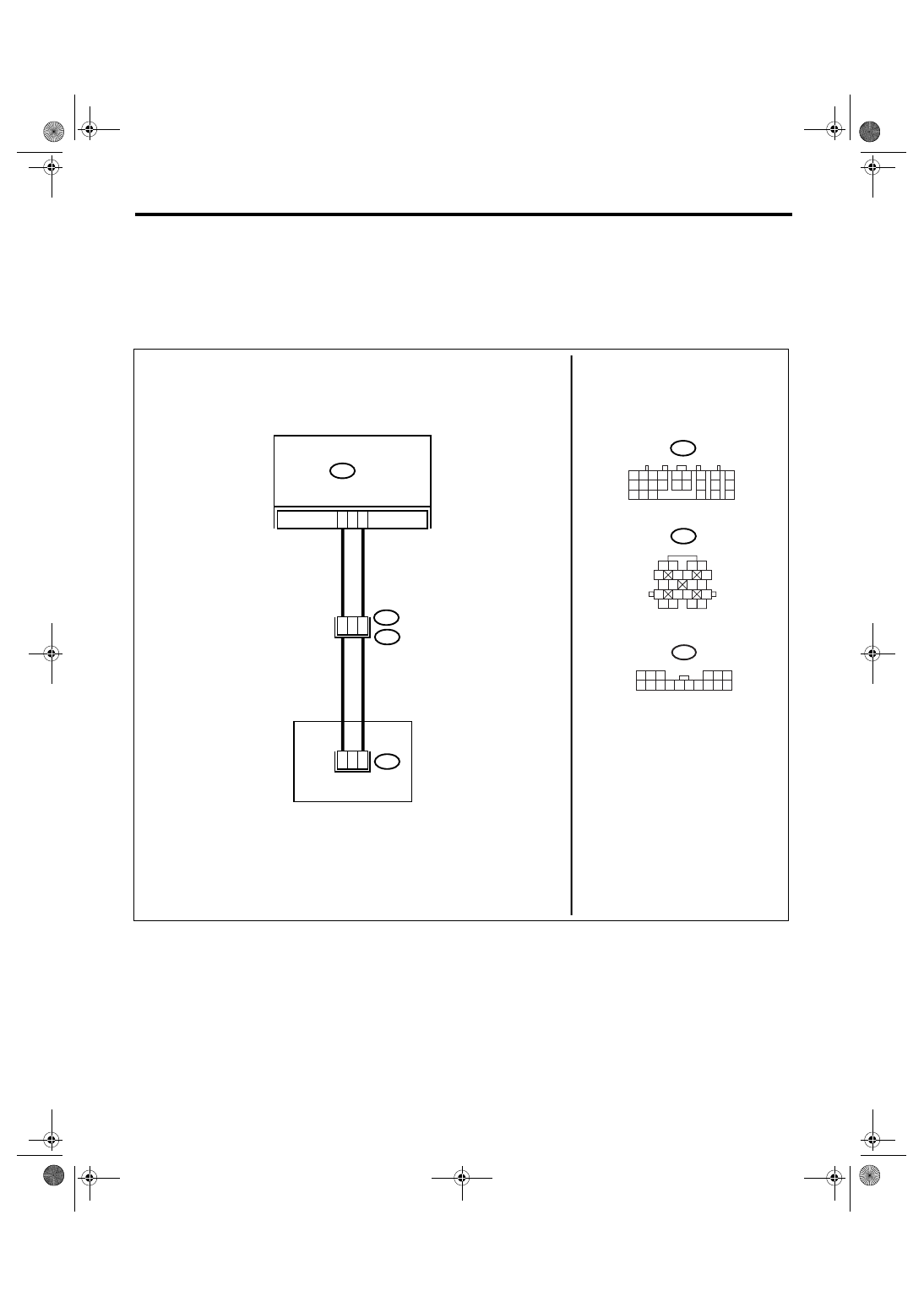
WIRING DIAGRAM:

AT-03179

B54

TCM

B54

TRANSMISSION

1 2

7

8

9

5 6

3 4

10 11 12
19 20 21

13

14 15

16

17

18

22

23

24

B11

1 2

5

6 7

8

13

14 15

16

9 10

11 12

3 4

17 18

19 20

2

B11

T4

13

1 2 3

6

8 9 10 11 12 13 14

4 5

15 16

T10

7

T10

16

1

5

12

5AT(diag)-40

AUTOMATIC TRANSMISSION (DIAGNOSTICS)

Diagnostic Procedure with Diagnostic Trouble Code (DTC)

Step

Check

Yes

No

1

CHECK HARNESS CONNECTOR BETWEEN 
TCM AND TRANSMISSION.
1) Turn the ignition switch to OFF.
2) Disconnect the connectors from TCM and 
transmission.
3) Measure the resistance of harness 
between TCM and transmission connector.

Connector & terminal

(B54) No. 13 — (B11) No. 12:
(B54) No. 2 — (B11) No. 5:

Is the resistance less than 1 
Ω?

Go to step 2.

Repair the open 
circuit of harness 
between TCM and 
transmission con-
nector.

2

CHECK ATF TEMPERATURE SENSOR.
1) Turn the ignition switch to OFF.
2) Connect the connectors to transmission 
and TCM.
3) Turn the ignition switch to ON and start 
engine.
4) Warm-up the transmission until the ATF 
temperature exceeds 80

°C (176°F).

NOTE:

If the ambient temperature is below 0

°C (32°F),

drive the vehicle until the ATF reaches its oper-
ating temperature.

5) Disconnect the connector from transmis-
sion.
6) Measure the resistance between transmis-
sion connector terminals.

Connector & terminal

(T4) No. 5 — (T4) No. 12:

Is the resistance 500 — 1,200 

Go to step 3.

Go to step 5.

3

CHECK ATF TEMPERATURE SENSOR.
Measure the resistance between transmission 
connector terminals.

Connector & terminal

(T4) No. 5 — (T4) No. 12:

Does the resistance value 
increase while the ATF temper-
ature decreases?

Go to step 4.

Go to step 5.

4

CHECK INPUT SIGNAL FOR TCM USING 
SUBARU SELECT MONITOR.
1) Connect the connector.
2) Turn the ignition switch to ON. (Engine 
OFF)
3) Read the ATF temperature using Subaru 
Select Monitor.

Does the ATF temperature 
gradually decrease?

Even if the SPORT 
indicator lights 
blinks, the system 
is in normal condi-
tion. A temporary 
poor contact of 
connector or har-
ness may be the 
cause. Repair the 
poor contact of 
harness between 
ATF temperature 
sensor and trans-
mission connector.

Go to step 6.

5AT(diag)-41

AUTOMATIC TRANSMISSION (DIAGNOSTICS)

Diagnostic Procedure with Diagnostic Trouble Code (DTC)

5

CHECK HARNESS CONNECTOR BETWEEN 
TRANSMISSION AND CONTROL VALVE 
BODY.
1) Turn the ignition switch to OFF.
2) Disconnect the connector from transmis-
sion.
3) Remove the transmission connector from 
bracket.
4) Jack-up the vehicle and place it on rigid 
racks.

NOTE:

Raise all wheels off floor.

5) Drain the ATF.

CAUTION:

Do not drain the ATF until it cools down.

6) Remove the oil pan, and disconnect the 
connector from control valve body connector.
7) Measure the resistance between transmis-
sion connector and control valve body connec-
tor.

Connector & terminal

(T4) No. 12 — (T10) No. 1:
(T4) No. 5 — (T10) No. 16:

Is the resistance less than 1 
Ω?

Replace the con-
trol valve body. 
<Ref. to 5AT-58, 
Control Valve 
Body.>

Repair the open 
circuit of harness 
between control 
valve body con-
nector and trans-
mission connector.

6

CHECK POOR CONTACT.

Is there poor contact in ATF 
temperature sensor circuit 1?

Repair the poor 
contact.

Replace the TCM. 
<Ref. to 5AT-61, 
Transmission Con-
trol Module 
(TCM).>

Step

Check

Yes

No

5AT(diag)-42

AUTOMATIC TRANSMISSION (DIAGNOSTICS)

Diagnostic Procedure with Diagnostic Trouble Code (DTC)

C: DTC P0713 TRANSMISSION FLUID TEMPERATURE SENSOR CIRCUIT HIGH 

INPUT

DTC DETECTING CONDITION:
Input signal circuit of TCM to ATF temperature sensor 1 is shorted.
TROUBLE SYMPTOM:
Excessive shift shock
WIRING DIAGRAM:

AT-03179

B54

TCM

B54

TRANSMISSION

1 2

7

8

9

5 6

3 4

10 11 12
19 20 21

13

14 15

16

17

18

22

23

24

B11

1 2

5

6 7

8

13

14 15

16

9 10

11 12

3 4

17 18

19 20

2

B11

T4

13

1 2 3

6

8 9 10 11 12 13 14

4 5

15 16

T10

7

T10

16

1

5

12


Content   ..  610  611  612  613   ..