Subaru Legacy (2005 year). Manual - part 601


  Index      Subaru     Subaru Legacy - service repair manual 2005 year


Search            


Content   ..  599  600  601  602   ..


Subaru Legacy (2005 year). Manual - part 601


5AT-103

AUTOMATIC TRANSMISSION

AT Main Case

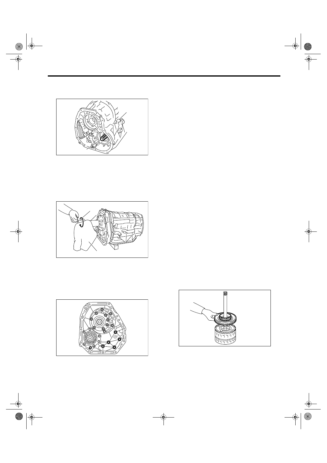
(3) Make sure the rear end of drive pinion shaft
is engaged to the spline of reduction driven
gear.

(4) Protect the input clutch shaft with a cloth,
and rotate to engage the spline of input clutch
and rear carrier using pliers.

NOTE:
Work with pressing the oil pump cover.

(5) Combine the oil pump cover with transmis-
sion main case.

Tightening torque:

41 N

m (4.2 kgf-m, 30.2 ft-lb)

23) Install the center differential carrier. <Ref. to
5AT-78, INSTALLATION, Center Differential Carri-
er.>
24) Install the reduction driven gear. <Ref. to 5AT-
76, INSTALLATION, Reduction Driven Gear.>

25) Install the extension case and intermediate
case. <Ref. to 5AT-71, INSTALLATION, Extension
Case and Intermediate Case.>
26) Install the control valve body. <Ref. to 5AT-58,
INSTALLATION, Control Valve Body.>
27) Install the converter case assembly into trans-
mission case assembly. <Ref. to 5AT-82, INSTAL-
LATION, Converter Case.>
28) Install the air breather hose. <Ref. to 5AT-68,
INSTALLATION, Air Breather Hose.>
29) Install the ATF filter pipe. <Ref. to 5AT-60, IN-
STALLATION, ATF Filter.>
30) Install the oil charge pipe with a O-ring. <Ref. to
5AT-69, INSTALLATION, Oil Charge Pipe.>
31) Install the torque converter assembly. <Ref. to
5AT-70, INSTALLATION, Torque Converter As-
sembly.>
32) Install the transmission assembly into vehicle.
<Ref. to 5AT-42, INSTALLATION, Automatic
Transmission Assembly.>
33) Perform the Clear Memory 2. <Ref. to 5AT(di-
ag)-19, CLEAR MEMORY MODE, OPERATION,
Subaru Select Monitor.>
34) Perform the inspection with driving the vehicle
at the end of repair work, and make sure there is no
faulty as below;
• Excessive shift shock
• Oil leakage from transmission body and etc.
• Occurrence of noise caused by interference etc.

NOTE:
If excessive shift shock is felt, execute the advance
operation of learning control. <Ref. to 5AT(diag)-
23, PROCEDURE, Learning Control.>

C: DISASSEMBLY

1. INPUT CLUTCH PACK ASSEMBLY

1) Remove the front sun gear.

(A) Drive pinion shaft

(A) Cloth

AT-02092

(A)

AT-02046

(A)

AT-01976

AT-02007

5AT-104

AUTOMATIC TRANSMISSION

AT Main Case

2) Remove the snap ring, and then remove the
front carrier.

3) Remove the input clutch assembly from rear in-
ternal gear.

D: ASSEMBLY

1. INPUT CLUTCH PACK ASSEMBLY

1) Assemble the input clutch assembly to rear inter-
nal gear.

2) Install the front carrier, and then install the snap
ring.

3) Install the front sun gear.

E: INSPECTION

1. FRONT, MIDDLE & REAR PLANETARY 
CARRIER ASSEMBLY

Check the following items.
• Visually inspect the tooth surface of planetary
gear, and replace with new one if damaged, broken
or excessively worn.
• Inspect the planetary carrier body for damage or
breakage.

2. INPUT CLUTCH

Check for damage on the drive plate, driven plate
and snap ring, and replace them as input clutch as-
sembly if damaged.

3. HIGH & LOW REVERSE CLUTCH AS-
SEMBLY

Check the clearance of high & low reverse clutch.
Measure the clearance “L” between snap ring and
retaining plate using thickness gauge. If the mea-
sured value is out of specification, replace them as
high & low reverse clutch assembly.

Specification:

1.8 — 2.2 mm (0.070 — 0.087 in)

4. DIRECT CLUTCH ASSEMBLY

Check the clearance of direct clutch.
Measure the clearance “L” between snap ring and
retaining plate using thickness gauge. If the mea-
sured value is out of specification, replace them as
direct clutch assembly.

AT-02008

AT-02009

AT-02009

AT-02008

AT-02007

AT-02010

L

5AT-105

AUTOMATIC TRANSMISSION

AT Main Case

Specification:

0.6 — 1.0 mm (0.024 — 0.039 in)

5. REVERSE BRAKE

Check the following items.
• Drive plate facing for wear or damage
• Snap ring for wear, return spring for breakage,
and spring retainer for deformation
• Lip seal and D-ring for damage
• Piston operation

F: ADJUSTMENT

1) Using the ST, measure the height “A” from the
AT main case mating surface to convex surface of
oil pump cover.
ST

499575400

GAUGE

2) Using the ST, measure the depth “B” from the
convex surface of oil pump cover to thrust bearing
transferring surface.
ST

499575400

GAUGE

3) Calculate the measured value from step 1) and
2), and then set the calculated value as “C”
Calculation formula: C = A 

− B

4) Using the ST, measure the depth “D” from the
AT main case mating surface to thrust bearing
transferring surface of front sun gear.
ST

499575400

GAUGE

5) Set the value as “E” which subtract the thickness
of ST (GAUGE) from the measured value on step
4).
Calculation formula:
E (mm) = D 

− 15

[E (in) = D 

− 0.59]

6) Calculation formula:
Select one thrust bearing from the table to adjust
clearance within 0.25 — 0.55 mm (0.0098 — 0.022
in).
When clearances are 0.25 mm (0.0098 in):
T (mm) = E 

− C + 0.03

[T (in) = E 

− C + 0.0012]

When clearances are 0.55 mm (0.022 in):
T (mm) = E 

− C − 0.27

[T (in) = E 

− C − 0.012]

T: Thrust bearing clearance
C: Distance from oil pump cover mating surface to
rear end of oil pump cover
E: Depth from mating surface of AT main case to
bearing surface of front sun gear

Example:
Assuming A is 39.50 mm (1.56 in), B is 16.20 mm
(0.64 in), then C will be 23.30 mm (0.92 in) by the
calculation.
When the D is 41.90 mm (1.65 in), subtract the
thickness of ST (GAUGE) from D, and the value E
will be 26.90 mm (1.06 in).
Calculation when clearance is 0.25 mm (0.0098 in)
T (mm) = 26.90 

− 23.30 + 0.03 = 3.63

[T (in) = 1.059 

− 0.917 + 0.0012 = 0.143]

Calculation when clearance is 0.55 mm (0.022 in)
T (mm) = 26.90 

− 23.30 − 0.27 = 3.33

[T (in) = 1.059 

− 0.917 − 0.012 = 0.131]

According to the calculation, the value “T” is found
to be 3.33 — 3.63 mm (0.131 — 0.143 in), therefore
select the thrust bearing with the thickness of 3.4
mm (0.134 in) or 3.6 mm (0.142 in) from the table.

AT-02011

L

AT-02012

ST

A

AT-02013

ST

B

AT-02014

ST

D

5AT-106

AUTOMATIC TRANSMISSION

AT Main Case

NOTE:
Calculation formula for “T” is applied when measur-
ing using ST (499575400 GAUGE). In the calcula-
tion without using ST, substitute the thickness of
collar used to calculate the value “E” on step 5).

Thrust bearing

Part No.

Thickness mm (in)

806548020

3.2 (0.126)

606548030

3.4 (0.134)

806548040

3.6 (0.142)

806548050

3.8 (0.150)

806548060

4.0 (0.157)

806548070

4.2 (0.165)


Content   ..  599  600  601  602   ..