Subaru Legacy (2005 year). Manual - part 558
 

  Index      Subaru     Subaru Legacy - service repair manual 2005 year


Search            


Content   ..  556  557  558  559   ..


Subaru Legacy (2005 year). Manual - part 558


4AT(diag)-69

AUTOMATIC TRANSMISSION (DIAGNOSTICS)

Diagnostic Procedure with Diagnostic Trouble Code (DTC)

Q: DTC P0753 SHIFT SOLENOID “A” ELECTRICAL

DTC DETECTING CONDITION:
Output signal circuit of low clutch duty solenoid is open or shorted.
TROUBLE SYMPTOM:
Excessive shift shock
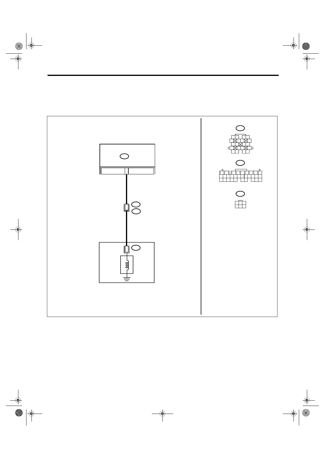
WIRING DIAGRAM:

AT-01487

B11

B55

AT3

1

2

3 4

5

6 7

8

9

13

14 15

20

19

17

16

10

11 12

18

9

B55

B11

AT3

T4

TCM

4

2

1

2

7

8

9

5

6

3

4

10 11 12

19 20 21

29 30 31

13 14 15 16 17

27 28

18

22 23 24 25 26

1

3

4 5 6

2

LOW CLUTCH
DUTY
SOLENOID

TRANSMISSION

4AT(diag)-70

AUTOMATIC TRANSMISSION (DIAGNOSTICS)

Diagnostic Procedure with Diagnostic Trouble Code (DTC)

Step

Check

Yes

No

1

CHECK HARNESS CONNECTOR BETWEEN 
TCM AND TRANSMISSION.
1) Turn the ignition switch to OFF.
2) Disconnect the connectors from TCM and 
transmission.
3) Measure the resistance of harness 
between TCM and transmission connector.

Connector & terminal

(B55) No. 9 — (B11) No. 4:

Is the resistance less than 1 
Ω?

Go to step 2.

Repair the open 
circuit of harness 
between TCM and 
transmission con-
nector.

2

CHECK HARNESS CONNECTOR BETWEEN 
TCM AND TRANSMISSION.
Measure the resistance of harness between 
TCM connector and transmission ground.

Connector & terminal

(B55) No. 9 — Chassis ground:

Is the resistance more than 1 
M

Ω?

Go to step 3.

Repair the short 
circuit of harness 
between TCM and 
transmission con-
nector.

3

CHECK LOW CLUTCH DUTY SOLENOID.
Measure the resistance between transmission 
connector terminals.

Connector & terminal

(T4) No. 4 — No. 20:

Is the resistance 2.0 — 6.0 

Ω? Go to step 5.

Go to step 4.

4

CHECK OUTPUT SIGNAL EMITTED FROM 
TCM USING SUBARU SELECT MONITOR.
1) Connect the connectors to TCM and trans-
mission.
2) Connect the Subaru Select Monitor to data 
link connector.
3) Start the engine, and turn the Subaru 
Select Monitor power switch to ON.
4) Warm-up the transmission until the ATF 
temperature exceeds approx. 80

°C (176°F).

NOTE:

If the ambient temperature is below 0

°C (32°F),

drive the vehicle until the ATF reaches its oper-
ating temperature.

5) Stop the engine and turn the ignition switch 
to ON (engine OFF).
6) Shift the select lever to “P” or “N” range, 
and depress the accelerator pedal.
7) Read the data of low clutch duty solenoid 
using Subaru Select Monitor.
• Low clutch duty solenoid is indicated in “%”.

Is the value 100%?

Go to step 5.

Go to step 7.

5

CHECK OUTPUT SIGNAL EMITTED FROM 
TCM USING SUBARU SELECT MONITOR.
1) Turn the ignition switch to ON (engine 
OFF).
2) Shift the select lever to “D” range.
3) Read the data of low clutch duty solenoid.

Is the value 0%?

Even if the SPORT 
indicator light is 
blinking, the cir-
cuit has returned 
to normal condi-
tion at this time. A 
temporary poor 
contact of connec-
tor or harness may 
be the cause. 
Repair the har-
ness or connector 
in transmission.

Go to step 6.

6

CHECK POOR CONTACT.

Is there poor contact in low 
clutch duty solenoid circuit?

Repair the poor 
contact.

Replace the TCM. 
<Ref. to 4AT-66, 
Transmission Con-
trol Module 
(TCM).>

4AT(diag)-71

AUTOMATIC TRANSMISSION (DIAGNOSTICS)

Diagnostic Procedure with Diagnostic Trouble Code (DTC)

7

CHECK LOW CLUTCH DUTY SOLENOID (IN 
TRANSMISSION).
1) Remove the transmission connector from 
bracket.
2) Drain the ATF.

CAUTION:

Do not drain ATF until it cools down.

3) Remove the oil pan, and disconnect the 
connector from control valve body.
4) Measure the resistance between low clutch 
duty solenoid connector and transmission 
ground.

Connector & terminal

(AT3) No. 2 — Transmission ground:

Is the resistance 2.0 — 6.0 

Ω? Go to step 8.

Replace the con-
trol valve body. 
<Ref. to 4AT-62, 
Control Valve 
Body.>

8

CHECK HARNESS CONNECTOR BETWEEN 
TRANSMISSION AND LOW CLUTCH DUTY 
SOLENOID.
Measure the resistance of harness between 
low clutch duty solenoid and transmission con-
nector.

Connector & terminal

(T4) No. 4 — (AT3) No. 2:

Is the resistance less than 1 
Ω?

Go to step 9.

Repair the open 
circuit of harness 
between low clutch 
duty solenoid and 
transmission con-
nector.

9

CHECK HARNESS CONNECTOR BETWEEN 
TRANSMISSION AND LOW CLUTCH DUTY 
SOLENOID.
Measure the resistance of harness between 
transmission connector and transmission 
ground.

Connector & terminal

(T4) No. 4 — Transmission ground:

Is the resistance more than 1 
M

Ω?

Even if the SPORT 
indicator light is 
blinking, the cir-
cuit has returned 
to normal condi-
tion at this time. A 
temporary poor 
contact of connec-
tor or harness may 
be the cause. 
Repair the har-
ness or connector 
in low clutch duty 
solenoid and 
transmission.

Repair the short 
circuit of harness 
between low clutch 
duty solenoid and 
transmission con-
nector.

Step

Check

Yes

No

4AT(diag)-72

AUTOMATIC TRANSMISSION (DIAGNOSTICS)

Diagnostic Procedure with Diagnostic Trouble Code (DTC)

R: DTC P0758 SHIFT SOLENOID “B” ELECTRICAL

DTC DETECTING CONDITION:
Output signal circuit of 2-4 brake duty solenoid is open or shorted.
TROUBLE SYMPTOM:
Excessive shift shock
WIRING DIAGRAM:

Step

Check

Yes

No

1

CHECK HARNESS CONNECTOR BETWEEN 
TCM AND TRANSMISSION.
1) Turn the ignition switch to OFF.
2) Disconnect the connectors from TCM and 
transmission.
3) Measure the resistance of harness 
between TCM and transmission connector.

Connector & terminal

(B55) No. 6 — (B11) No. 3:

Is the resistance less than 1 
Ω?

Go to step 2.

Repair the open 
circuit of harness 
between TCM and 
transmission con-
nector.

2

CHECK HARNESS CONNECTOR BETWEEN 
TCM AND CHASSIS GROUND.
Measure the resistance of harness between 
TCM connector and chassis ground.

Connector & terminal

(B55) No. 6 — Chassis ground:

Is the resistance more than 1 
M

Ω?

Go to step 3.

Repair the short 
circuit of harness 
between TCM and 
transmission con-
nector.

3

CHECK 2-4 BRAKE DUTY SOLENOID.
Measure the resistance between transmission 
connector terminals.

Connector & terminal

(T4) No. 3 — No. 20:

Is the resistance 2.0 — 6.0 

Ω? Go to step 4.

Go to step 7.

AT-01488

6

B55

B11

AT3

T4

TCM

B11

1

2

3 4

5

6 7

8

9

13

14 15

20

19

17

16

10

11 12

18

3

6

B55

AT3

1

2

7

8

9

5

6

3

4

10 11 12

19 20 21

29 30 31

13 14 15 16 17

27 28

18

22 23 24 25 26

1

3

4 5 6

2

TRANSMISSION

2-4 BRAKE
DUTY
SOLENOID


Content   ..  556  557  558  559   ..