Subaru Legacy (2005 year). Manual - part 532
4AT-109
AUTOMATIC TRANSMISSION
Drive Pinion Shaft Assembly
39.Drive Pinion Shaft Assembly
A: REMOVAL
1) Remove the transmission assembly from vehi-
cle. <Ref. to 4AT-39, REMOVAL, Automatic Trans-
mission Assembly.>
2) Pull out the torque converter clutch assembly.
<Ref. to 4AT-81, REMOVAL, Torque Converter
Clutch Assembly.>
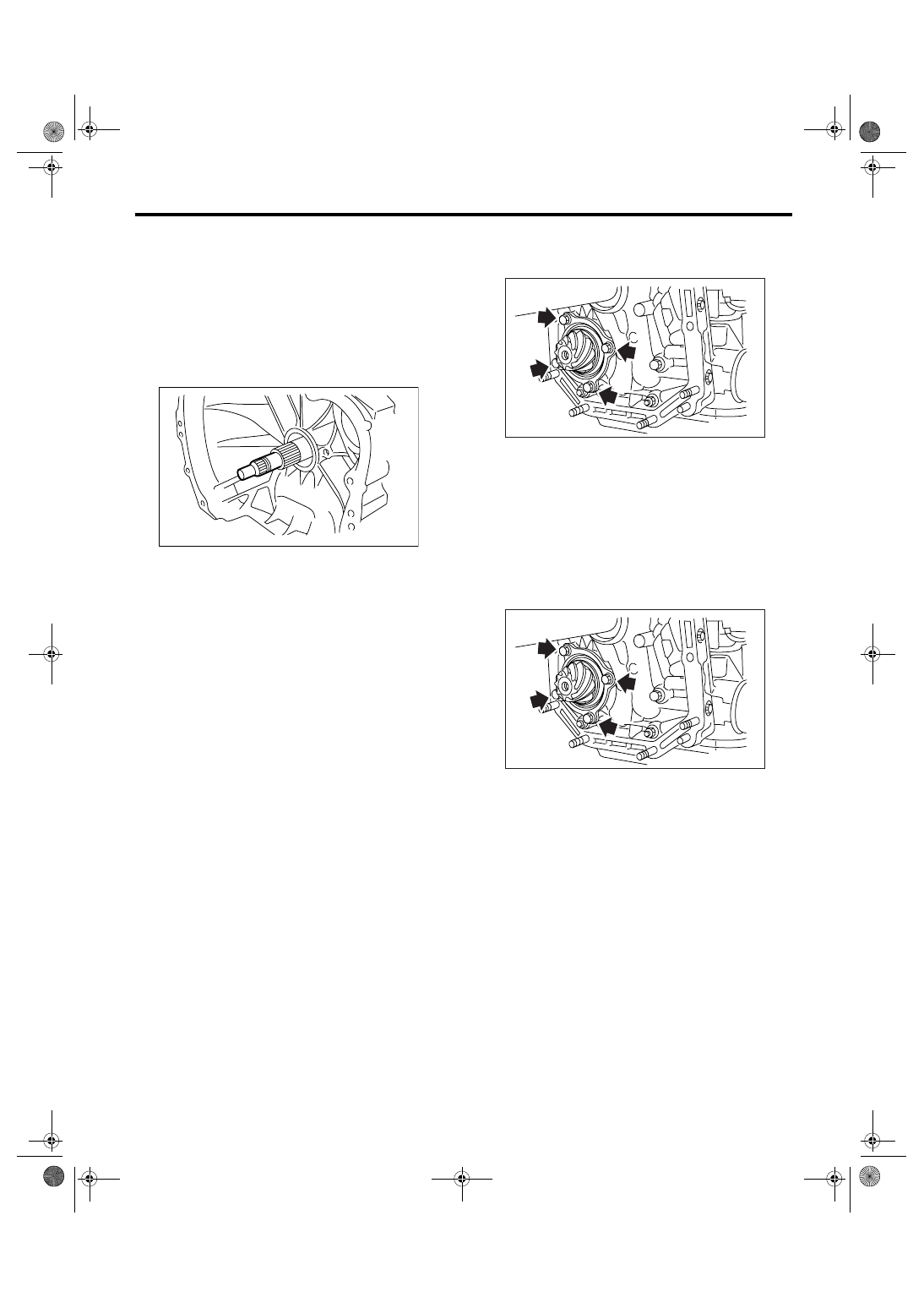
3) Remove the input shaft.
4) Lift up the lever on rear side of transmission har-
ness connector, and then disconnect it from the
stay.
5) Disconnect the inhibitor switch connector from
stay.
6) Disconnect the air breather hose. <Ref. to 4AT-
79, REMOVAL, Air Breather Hose.>
7) Remove the oil charge pipe. <Ref. to 4AT-80,
REMOVAL, Oil Charge Pipe.>
8) Remove the oil cooler inlet and outlet pipes.
<Ref. to 4AT-68, REMOVAL, ATF Cooler Pipe and
Hose.>
9) Separate the converter case and transmission
case part. <Ref. to 4AT-102, REMOVAL, Converter
Case.>
10) Separate the transmission case and extension
case part. <Ref. to 4AT-83, REMOVAL, Extension
Case.>
11) Remove the reduction drive gear. (MP-T mod-
el) <Ref. to 4AT-97, REMOVAL, Reduction Drive
Gear.>
12) Remove the center differential carrier. (VTD
model) <Ref. to 4AT-99, REMOVAL, Center Differ-
ential Carrier.>
13) Remove the reduction driven gear. <Ref. to
4AT-95, REMOVAL, Reduction Driven Gear.>
14) Remove the drive pinion shaft mounting bolt
and remove the drive pinion shaft assembly from oil
pump housing.
B: INSTALLATION
1) Assemble the drive pinion assembly to oil pump
housing.
NOTE:
• Be careful not to bend the shim.
• Be careful not to press-fit the pinion into housing
bore.
Tightening torque:
40 N
⋅
m (4.1 kgf-m, 29.5 ft-lb)
2) Combine the torque converter case with trans-
mission case. <Ref. to 4AT-102, INSTALLATION,
Converter Case.>
3) Install the reduction driven gear. <Ref. to 4AT-
95, INSTALLATION, Reduction Driven Gear.>
4) Install the reduction drive gear. (MP-T model)
<Ref. to 4AT-97, INSTALLATION, Reduction Drive
Gear.>
5) Install the center differential carrier. (VTD model)
<Ref. to 4AT-99, INSTALLATION, Center Differen-
tial Carrier.>
6) Combine the transmission case with extension
case, and then install the rear vehicle speed sen-
sor. <Ref. to 4AT-83, INSTALLATION, Extension
Case.>
7) Insert the inhibitor switch and transmission con-
nector to stay.
8) Install the oil cooler inlet and outlet pipes. <Ref.
to 4AT-70, INSTALLATION, ATF Cooler Pipe and
Hose.>
9) Install the oil charge pipe with O-ring.
AT-00114
AT-01252
AT-01252