Subaru Legacy (2005 year). Manual - part 531


  Index      Subaru     Subaru Legacy - service repair manual 2005 year


Search            


Content   ..  529  530  531  532   ..


Subaru Legacy (2005 year). Manual - part 531


4AT-105

AUTOMATIC TRANSMISSION

Oil Pump Housing

2) Install the converter case assembly into trans-
mission case assembly. <Ref. to 4AT-81, INSTAL-
LATION, Torque Converter Clutch Assembly.>
3) Install the reduction driven gear. <Ref. to 4AT-
95, INSTALLATION, Reduction Driven Gear.>
4) Install the reduction drive gear. (MP-T model)
<Ref. to 4AT-97, INSTALLATION, Reduction Drive
Gear.>
5) Install the center differential carrier. (VTD model)
<Ref. to 4AT-99, INSTALLATION, Center Differen-
tial Carrier.>
6) Combine the transmission case with extension
case, and then install the rear vehicle speed sen-
sor. <Ref. to 4AT-83, INSTALLATION, Extension
Case.>
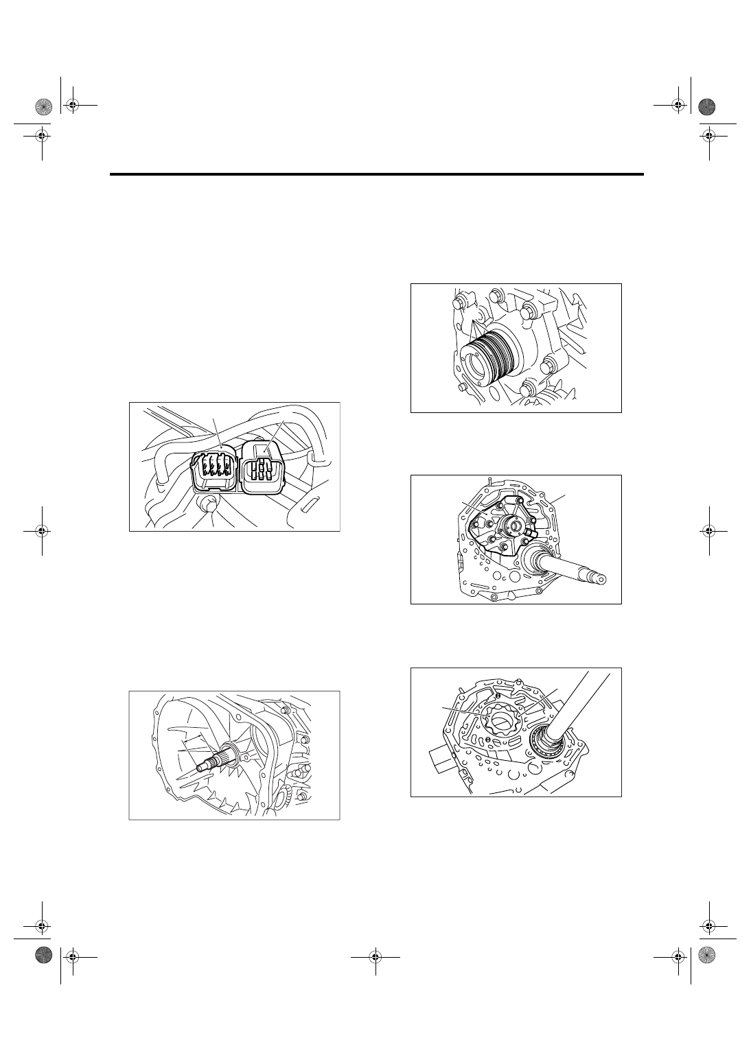
7) Insert the inhibitor switch and transmission con-
nector to stay.

8) Install the oil cooler pipe. <Ref. to 4AT-70, IN-
STALLATION, ATF Cooler Pipe and Hose.>
9) Install the oil charge pipe with a O-ring. <Ref. to
4AT-80, INSTALLATION, Oil Charge Pipe.>
10) Insert the input shaft while rotating it lightly by
hand, and then check the protrusion amount.

Normal protrusion A:

50 — 55 mm (1.97 — 2.17 in)

11) Install the torque converter clutch assembly.
<Ref. to 4AT-81, INSTALLATION, Torque Convert-
er Clutch Assembly.>

12) Install the transmission assembly into vehicle.
<Ref. to 4AT-42, INSTALLATION, Automatic
Transmission Assembly.>

C: DISASSEMBLY

1. OIL PUMP COVER

1) Remove four seal rings.

2) Remove the cover by lightly tapping the end of
stator shaft.

3) Remove the inner and outer rotor.

(A) Transmission connector

(B) Inhibitor switch connector

AT-01351

(B)

(A)

AT-03204

A

(A) Seal ring

(A) Oil pump cover

(B) Oil pump housing

(A) Inner rotor

(B) Outer rotor

AT-00189

(A)

AT-00190

(A)

(B)

AT-01036

(A)

(B)

4AT-106

AUTOMATIC TRANSMISSION

Oil Pump Housing

2. OIL SEAL RETAINER

1) Remove the oil seal retainer.

2) Remove the O-ring.

3) Remove the oil seal from oil seal retainer.

D: ASSEMBLY

1. OIL PUMP COVER

1) Install the oil pump rotor assembly to oil pump
housing.

2) Align both pivots with the pivot holes of cover,
and then install the oil pump cover being careful not
to apply excessive force to the pivots.

Tightening torque:

25 N

m (2.5 kgf-m, 18.4 ft-lb)

3) After assembling, turn the oil pump shaft to
check the smooth rotation of rotor.

(A) Oil seal retainer

(B) Drive pinion shaft

(A) O-ring

(A) Oil seal

(B) Oil seal retainer

AT-00183

(A)

(B)

AT-00186

(A)

AT-00185

(A)

(B)

(A) Inner rotor

(B) Outer rotor

(A) Oil pump cover

(B) Oil pump housing

AT-01036

(A)

(B)

AT-00190

(A)

(B)

4AT-107

AUTOMATIC TRANSMISSION

Oil Pump Housing

4) Apply vaseline to oil seal retainer and new seal
ring, and install them. After installing, adjust the
tooth contact and backlash of drive pinion. <Ref. to
4AT-108, ADJUSTMENT, Oil Pump Housing.>

2. OIL SEAL RETAINER

1) Apply ATF to new oil seals (two), and install
them to oil seal retainer in proper direction using
ST.
ST

499247300

INSTALLER

2) Apply ATF to new O-ring, and install it to oil seal
retainer. Install the seal to oil pump housing bore.

3) Install the oil seal and secure it using three bolts
being careful not to damage oil seal lip.

Tightening torque:

7 N

m (0.7 kgf-m, 5.1 ft-lb)

E: INSPECTION

1) Check the seal ring and oil seal for breaks or
damages.
2) Check other parts for dents or abnormalities.
3) Selection of oil pump rotor assembly

(1) Tip clearance
Install the inner rotor and outer rotor to oil pump.
With rotor gears facing each other, measure the
crest-to-crest clearance.

Tip clearance:

0.02 — 0.15 mm (0.0008 — 0.0059 in)

(2) Side clearance
Set a depth gauge to oil pump housing, then
measure the oil pump housing-to-rotor clear-
ance.

(A) Seal ring (Black)

(B) Seal ring (Brown)

(A) Oil seal

(B) Oil seal retainer

(A) O-ring

AT-01307

(A)

(B)

AT-00185

(A)

(B)

AT-00186

(A)

(A) Oil seal retainer

(B) Drive pinion shaft

(A) Thickness gauge

(B) Inner rotor

(C) Outer rotor

AT-00183

(A)

(B)

AT-01038

(B)

(C)

(A)

4AT-108

AUTOMATIC TRANSMISSION

Oil Pump Housing

Side clearance:

0.02 — 0.04 mm (0.0008 — 0.0016 in)

(3) If the depth and/or side clearance are not
within the specification, replace the rotor assem-
bly.

Measure the total end play and adjust it within
specification. <Ref. to 4AT-108, ADJUSTMENT,
Oil Pump Housing.>

F: ADJUSTMENT

1) Using the ST, measure the depth from the mat-
ing surface of transmission to the recessed portion
“L” of high clutch drum.
ST

398643600

GAUGE

2) Using the ST, measure the height from oil pump
housing mating surface to the top surface of oil
pump cover with thrust needle bearing.

ST

398643600

GAUGE

3) Calculation of total end play
Select the suitable bearing race from the table be-
low so that clearance C to be within 0.25 to 0.55
mm (0.0098 to 0.0217 in).
C = (L + G) 

−2

4) After completing the total end play adjustment,
insert the bearing race in recess of the high clutch.
Install the thrust needle bearing to oil pump cover
using vaseline.
5) After correctly install the new gasket to the case
mating surface, carefully install the oil pump hous-
ing assembly. Be careful to avoid hitting the drive
pinion against the inside of case.
6) Install both parts with dowel pins aligned. Make
sure no clearance at mating surface. 

(A) Depth gauge

(B) Inner rotor

(C) Outer rotor

Oil pump rotor ASSY

Part No.

Thickness mm (in)

15008AA060

11.37 — 11.38 (0.4476 — 0.4480)

15008AA070

11.38 — 11.39 (0.4480 — 0.4484)

15008AA080

11.39 — 11.40 (0.4484 — 0.4488)

AT-01039

(A)

(B)

(C)

AT-00194

L

ST

C

Clearance between concave portion of high 
clutch and end of clutch drum support

L

Depth from case mating surface to concave por-
tion of high clutch

G

Gasket thickness [0.28 mm (0.0110 in)]

2

Height from housing mating surface to upper 
surface of clutch drum support

Thrust needle bearing

Part No.

Thickness mm (in)

806528050

4.1 (0.161)

806528060

4.3 (0.169)

806528070

4.5 (0.177)

806528080

4.7 (0.185)

806528090

4.9 (0.193)

806528100

5.1 (0.201)

AT-00195

ST

AT-00196

G

L


Content   ..  529  530  531  532   ..