Subaru Legacy (2005 year). Manual - part 518
4AT-53
AUTOMATIC TRANSMISSION
Inhibitor Switch
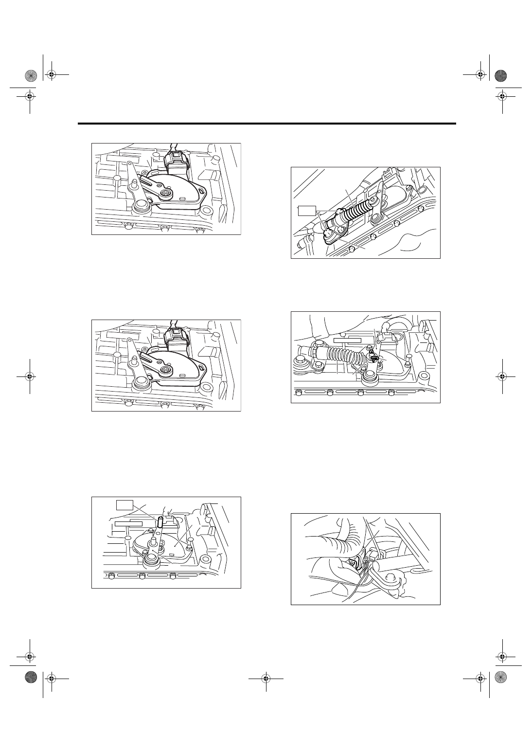
12) Remove the inhibitor switch from transmission.
13) Disconnect the inhibitor switch harness con-
nector from inhibitor switch.
D: INSTALLATION
1) Connect the inhibitor switch harness connector
to inhibitor switch.
2) Install the inhibitor switch to transmission case.
3) Move the range select lever to neutral position.
4) Tighten the three inhibitor switch securing bolts
using ST.
ST
499267300
STOPPER PIN
Tightening torque:
3.4 N
⋅
m (0.35 kgf-m, 2.5 ft-lb)
5) Install the select cable to range select lever.
6) Install the plate assembly to transmission.
Tightening torque:
T: 25 N
⋅
m (2.5 kgf-m, 18.4 ft-lb)
7) Install the snap pin washers to range select le-
ver.
8) Install the front and center exhaust pipe.
<Ref. to EX(H4SO 2.0)-7, INSTALLATION, Front
Exhaust Pipe.>
9) Lower the vehicle.
10) Install the inhibitor switch connector to the stay.
11) Connect the inhibitor switch connector.
(A) Inhibitor switch
(A) Inhibitor switch
(A) Inhibitor switch
(B) Range select lever
AT-00038
(A)
AT-00038
(A)
(A)
AT-00039
(B)
ST
(A) Select cable
(B) Plate ASSY
(A) Range select lever
(B) Snap ring
(C) Select cable
(D) Washer
(A) Inhibitor switch connector
AT-00040
( A )
( B )
T
AT-00034
(C)
(B)
(A)
(D)
AT-01350
(A)