Subaru Legacy (2005 year). Manual - part 486


  Index      Subaru     Subaru Legacy - service repair manual 2005 year


Search            


Content   ..  484  485  486  487   ..


Subaru Legacy (2005 year). Manual - part 486


EN(H6DO)(diag)-257

ENGINE (DIAGNOSTICS)

Diagnostic Procedure with Diagnostic Trouble Code (DTC)

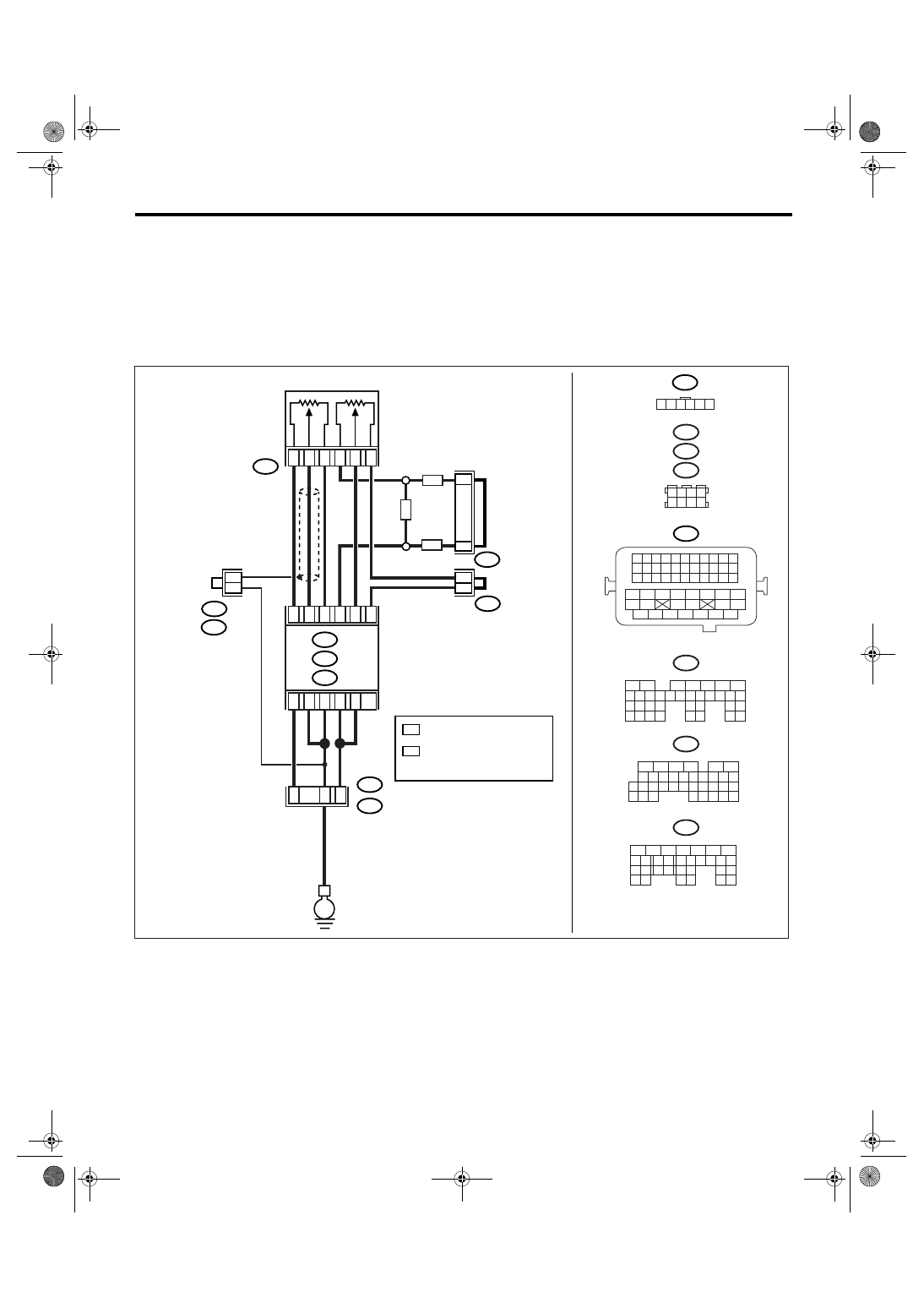
DB:DTC P2128 THROTTLE/PEDAL POSITION SENSOR/SWITCH “E” CIRCUIT 

HIGH INPUT

DTC DETECTING CONDITION:
Immediately at fault recognition
TROUBLE SYMPTOM:
• Erroneous idling
• Poor driving performance
WIRING DIAGRAM:

EN-03506

B315

E

C:

ECM

B136

B137

D:

B83

B315

ACCELERATOR

PEDAL POSITION

SENSOR

*

*

3

5

4

1

2

6

C15

C17

C34

C16

C28

C35

D1

D2

B21

E2

B1

B138

1 2 3 4
5 6 7 8

MAIN

SUB

B21

1 2 3 4

12 13 14 15

5 6 7 8

16 17 18 19

9 10 11

20 21 22

23 24 25 26 27 28 29 30 31 32 33

35

34

37

36

39

38

41

40

43

42

44

45

47

46

49

48

51

50

53

52

54

B137

5

6

7

8

2

1

9

4

3

10

22 23

11 12 13 14 15

24 25

26

16 17

18 19 20 21

27

28 29

30 31

B136

5

6

7 8

2

1

9

4

3

10

24

22 23

25

11 12 13 14 15

26 27

28

16

17 18 19 20 21

33 34

29

32

30

31

35

B135

5

6

7

8

2

1

9

4

3

10

24

22 23

25

11 12 13 14 15

26 27

28

16 17 18 19

20 21

29 30 31

32 33

34 35

B:

C:

D:

B122

B83

B122

D3

B: B135

B4

37

36

35

1 2 3 4 5 6

*

*

1
1

1

*

2

*

2

1

 : TERMINAL No. 
   RANDOM ARRANGEMENT

*

1

LHD

RHD

RHD

*

: TERMINAL No. 
  RANDOM ARRANGEMENT 
  AMONG 3,4,7, AND 8

2

B122

B138

: LHD

: RHD

EN(H6DO)(diag)-258

ENGINE (DIAGNOSTICS)

Diagnostic Procedure with Diagnostic Trouble Code (DTC)

Step

Check

Yes

No

1

CHECK ACCELERATOR PEDAL POSITION 
SENSOR OUTPUT.
1) Turn the ignition switch to ON.
2) Read the data of sub accelerator pedal 
position sensor signal using Subaru Select 
Monitor.

NOTE:

For detailed operation procedure, refer to
“READ CURRENT DATA FOR ENGINE”. <Ref.
to EN(H6DO)(diag)-26, Subaru Select Moni-
tor.>

Is the voltage less than 4.8 V? Go to step 2.

Go to step 3.

2

CHECK POOR CONTACT.
Check poor contact in connector between 
ECM and accelerator pedal position sensor.

Is there poor contact?

Repair the poor 
contact.

Temporary poor 
contact occurred, 
but it is normal at 
present.

3

CHECK HARNESS BETWEEN ECM AND AC-
CELERATOR PEDAL POSITION SENSOR.
1) Turn the ignition switch to OFF.
2) Disconnect the connector from ECM.
3) Disconnect the connectors from accelerator 
pedal position sensor.
4) Measure the resistance between ECM con-
nector and accelerator pedal position sensor 
connector.

Connector & terminal

(B136) No. 35 — (B315) No. 6:

Is the resistance less than 1 
Ω?

Go to step 4.

Repair the open 
circuit of harness 
connector.

4

CHECK HARNESS BETWEEN ECM AND AC-
CELERATOR PEDAL POSITION SENSOR.
1) Connect the ECM connector.
2) Measure the resistance between accelera-
tor pedal position sensor connector and engine 
ground.

Connector & terminal

(B315) No. 6 — Engine ground:

Is the resistance less than 5 
Ω?

Go to step 5.

Repair the poor 
contact in ECM 
connector. 
Replace the ECM 
if defective. <Ref. 
to FU(H6DO)-34, 
Engine Control 
Module (ECM).>

5

CHECK HARNESS BETWEEN ECM AND AC-
CELERATOR PEDAL POSITION SENSOR.
1) Connect the ECM connector.
2) Turn the ignition switch to ON.
3) Measure the voltage between accelerator 
pedal position sensor connector and engine 
ground.

Connector & terminal

(B315) No. 2 (+) — Engine ground (

):

Is the voltage less than 6 V?

Go to step 6.

Repair the battery 
short circuit of har-
ness between 
ECM connector 
and accelerator 
pedal position sen-
sor connector.

6

CHECK HARNESS BETWEEN ECM AND AC-
CELERATOR PEDAL POSITION SENSOR.
1) Turn the ignition switch to OFF.
2) Disconnect the connector from ECM.
3) Measure the resistance between ECM con-
nectors.

Connector & terminal

(B136) No. 28 — (B136) No. 15:
(B136) No. 28 — (B136) No. 16:

Is the resistance more than 1 
M

Ω?

Repair the poor 
contact in acceler-
ator pedal position 
sensor connector. 
Replace the accel-
erator pedal posi-
tion sensor if 
defective.

Repair the short 
circuit to sensor 
power supply.

EN(H6DO)(diag)-259

ENGINE (DIAGNOSTICS)

Diagnostic Procedure with Diagnostic Trouble Code (DTC)

DC:DTC P2135 THROTTLE/PEDAL POSITION SENSOR/SWITCH “A” / “B” 

VOLTAGE CORRELATION

DTC DETECTING CONDITION:
Immediately at fault recognition
TROUBLE SYMPTOM:
• Erroneous idling
• Poor driving performance
WIRING DIAGRAM:

EN-03499

SBF-7

B135

B:

B137

B136

D:

B362

E1

B20

B83

B122

C:

E

E

E

D6

B35

38

39

20

19

16

15

*
*

E2

B21

E57

4

6

1

2

3

5

D4

D5

C35

C16

B1

B4

D1

D2

D3

36

35

37

C29

C18

ECM

5
6

B362

B20

B21

E57

B122

B83

B138

1 2

7 8

3
4

5
6

1 2 3 4 5 6 7 8 9 10 11

12 13 14 15 16 17 18 19 20 21 22
23 24 25

34 35

36 37 38 39 40 41

48 49

50 51 52 53 54

42 43

44 45

46 47

26 27 28 29 30 31 32 33

1 2 3 4
5 6 7 8

1

2

7

8 9

5

6

3

4

10 11 12

19 20 21

29

30 31

13 14 15 16 17

27

28

18

22 23

24 25

26

1

2

8 9

5

6

3

4

10 11 12

19 20 21

29 30

31

13 14 15 16

17

27

28

18

22 23 24 25 26

7

32 33 34 35

B136

C:

B137

D:

BATTERY

MAIN RELAY

ELECTRONIC
THROTTLE 
CONTROL RELAY

ELECTRONIC
THROTTLE CONTROL

1 2 3 4
5 6 7 8
9 10 11 12

13 14 15 16

1 2 3 4 5 6

*

*

1

*

2

*

2

1

1

1

*

1  : TERMINAL No. 

   RANDOM ARRANGEMENT

B135

5

6

7

8

2

1

9

4

3

10

24

22 23

25

11 12 13 14 15

26 27

28

16 17 18 19

20 21

29 30 31

32 33

34 35

B:

8

7

RHD

RHD

LHD

*

: TERMINAL No. 
  RANDOM ARRANGEMENT 
  AMONG 3,4,7, AND 8

2

B122

B138

: LHD

: RHD

EN(H6DO)(diag)-260

ENGINE (DIAGNOSTICS)

Diagnostic Procedure with Diagnostic Trouble Code (DTC)

Step

Check

Yes

No

1

CHECK SENSOR OUTPUT.
1) Turn the ignition switch to ON.
2) Read the data of main throttle sensor signal 
using Subaru Select Monitor.

NOTE:

For detailed operation procedure, refer to
“READ CURRENT DATA FOR ENGINE”. <Ref.
to EN(H6DO)(diag)-26, Subaru Select Moni-
tor.>

Is the voltage more than 0.4 V? Go to step 2.

Go to step 4.

2

CHECK SENSOR OUTPUT.
Read the data of sub throttle sensor signal 
using Subaru Select Monitor.

NOTE:

For detailed operation procedure, refer to
“READ CURRENT DATA FOR ENGINE”. <Ref.
to EN(H6DO)(diag)-26, Subaru Select Moni-
tor.>

Is the voltage more than 0.8 V? Go to step 3.

Go to step 4.

3

CHECK POOR CONTACT.
Check poor contact in connector between 
ECM and electronic throttle control.

Is there poor contact?

Repair the poor 
contact.

Go to step 14.

4

CHECK HARNESS BETWEEN ECM AND 
ELECTRONIC THROTTLE CONTROL.
1) Turn the ignition switch to OFF.
2) Disconnect the connector from ECM.
3) Disconnect the connectors from electronic 
throttle control.
4) Measure the resistance between ECM con-
nector and electronic throttle control connector.

Connector & terminal

(B136) No. 18 — (E57) No. 6:
(B136) No. 29 — (E57) No. 4:
(B136) No. 16 — (E57) No. 5:

Is the resistance less than 1 
Ω?

Go to step 5.

Repair the open 
circuit of harness 
connector.

5

CHECK HARNESS BETWEEN ECM AND 
ELECTRONIC THROTTLE CONTROL.
Measure the resistance between ECM connec-
tor and chassis ground.

Connector & terminal

(B136) No. 18 — Chassis ground:
(B136) No. 29 — Chassis ground:
(B136) No. 16 — Chassis ground:

Is the resistance more than 1 
M

Ω?

Go to step 6.

Repair the ground 
short circuit of har-
ness.

6

CHECK SENSOR POWER SUPPLY.
1) Connect the ECM connector.
2) Turn the ignition switch to ON.
3) Measure the voltage between electronic 
throttle control connector and engine ground.

Connector & terminal

(E57) No. 5 (+) — Engine ground (

):

Is the voltage 4.5 — 5.5 V?

Go to step 7.

Repair the poor 
contact in ECM 
connector. 
Replace the ECM 
if defective. <Ref. 
to FU(H6DO)-34, 
Engine Control 
Module (ECM).>

7

CHECK SHORT CIRCUIT IN ECM.
1) Turn the ignition switch to OFF.
2) Measure the resistance between electronic 
throttle control connector and engine ground.

Connector & terminal

(E57) No. 6 — Engine ground:
(E57) No. 4 — Engine ground:

Is the resistance more than 10 
Ω?

Go to step 8.

Repair the poor 
contact in ECM 
connector. 
Replace the ECM 
if defective. <Ref. 
to FU(H6DO)-34, 
Engine Control 
Module (ECM).>


Content   ..  484  485  486  487   ..