Subaru Legacy (2005 year). Manual - part 217
EN(H4SO 2.5)(diag)-153
ENGINE (DIAGNOSTICS)
Diagnostic Procedure with Diagnostic Trouble Code (DTC)
AH:DTC P0335 CRANKSHAFT POSITION SENSOR “A” CIRCUIT
DTC DETECTING CONDITION:
Immediately at fault recognition
TROUBLE SYMPTOM:
• Engine stalls.
• Failure of engine to start
CAUTION:
After repair or replacement of faulty parts, conduct Clear Memory Mode <Ref. to EN(H4SO 2.5)(diag)-
40, Clear Memory Mode.> and Inspection Mode <Ref. to EN(H4SO 2.5)(diag)-33, Inspection Mode.>.
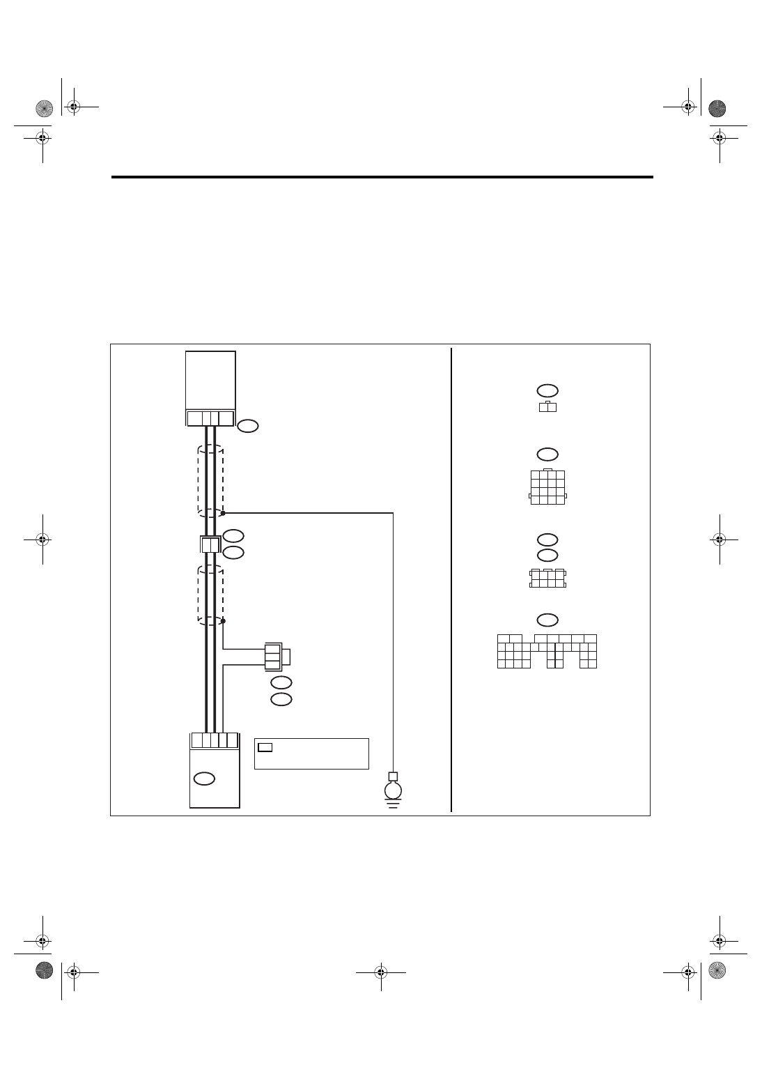
WIRING DIAGRAM:
• EC, EK, EH, ER and K4 model
• KA and KS model
NOTE:
Fuel injection system for KA and KS model is the same as 2.0 L model. Refer to EN(H4SO 2.0) section.
EN-03463
1
2
8
7
22
31
B20
E1
E10
E10
1 2
B135
ECM
CRANKSHAFT
POSITION
SENSOR
10
E
B20
1 2 3 4
5 6 7 8
B122
B138
B135
5
6
7
8
2
1
9
4
3
10
24
22 23
25
11 12 13 14 15
26 27
28
16 17 18 19
20 21
29 30 31
32 33
34 35
B122 : RHD
B138 : LHD
1 2 3 4
5 6 7 8
9 10 11 12
14
13
15 16
*
: TERMINAL No. RANDOM
ARRANGEMENT
AMONG 3,4,7, AND 8
*
*