Subaru Legacy (2005 year). Manual - part 1029


  Index      Subaru     Subaru Legacy - service repair manual 2005 year


Search            


Content   ..  1027  1028  1029  1030   ..


Subaru Legacy (2005 year). Manual - part 1029


IM(diag)-21

IMMOBILIZER (DIAGNOSTICS)

Diagnostic Procedure with Diagnostic Trouble Code (DTC)

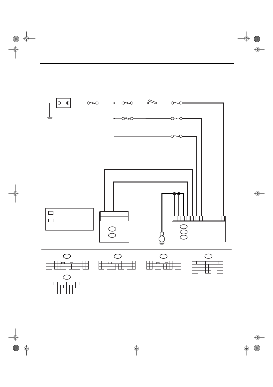
D: DTC P1572 IMM CIRCUIT FAILURE (EXCEPT ANTENNA CIRCUIT)

DTC DETECTING CONDITION:
Communication failure between body integrated module and ECM
WIRING DIAGRAM:

MAIN SBF

SBF-8

SBF-3

BATTERY

F/B No.12

IGNITION

SWITCH

A1

B28

B18

C9

C2

B7

C8

E

F/B No.7

M/B No.8

BODY INTEGRATED MODULE

i84

A:

B280

B:

B281

C:

B22

5 6 7

8

2

1

9

4

3

10

24

22 23

25

11 12 13 14 15

26

27 28

16 17 18 19

20 21

B281

i84

1 2

3 4

5 6

7 8

9 10 11 12 13 14 15 16 17 18 19 20 21 22 23

24 25

26 27 28 29

30 31 32 33

34 35

5

4

6 7

8

2

1

9

3

10

22

23

11 12 13 14 15

24 25

26 27

16 17 18

28 29

19 20

21

30

B280

A:

C:

B:

B137

5

6

7

8

2

1

9

4

3

10

22 23

11 12 13 14 15

24 25

26

16 17

18 19 20 21

27

28 29

30 31

D:

D19

D27

B33

B25

1

*

2

*

1

*

2

*

: 2.0 L NON-TURBO MODEL AND
  2.5 L KS, KA MODEL

: 2.0 L TURBO MODEL,
  3.0 L MODEL AND
  2.5 L EC, K4, EK MODEL

B135

5

6

7

8

2

1

9

4

3

10

24

22 23

25

11 12 13 14 15

26 27

28

16 17 18 19

20 21

29 30 31

32 33

34 35

B:

B137

D:

ECM

B135

B:

IM-00139

IM(diag)-22

IMMOBILIZER (DIAGNOSTICS)

Diagnostic Procedure with Diagnostic Trouble Code (DTC)

Step

Check

Yes

No

1

CHECK BODY INTEGRATED MODULE 
POWER SUPPLY CIRCUIT.
1) Turn the ignition switch to OFF.
2) Disconnect the harness connector from 
body integrated module.
3) Measure the voltage between body inte-
grated module harness connector terminal and 
chassis ground.

Connector & terminal

(B280) No. 7 (+) — Chassis ground (

):

(B281) No. 2 (+) — Chassis ground (

):

Is the voltage more than 10 V? Go to step 2.

Check the harness 
for open or short 
circuit between 
body integrated 
module and fuse.

2

CHECK BODY INTEGRATED MODULE 
POWER SUPPLY CIRCUIT.
1) Turn the ignition switch to ON. (engine 
OFF)
2) Measure the voltage between body inte-
grated module harness connector terminal and 
chassis ground.

Connector & terminal

(i84) No. 1 (+) — Chassis ground (

):

Is the voltage more than 10 V? Go to step 3.

Check the harness 
for open or short 
circuit between 
body integrated 
module and igni-
tion switch.

3

CHECK BODY INTEGRATED MODULE 
GROUND CIRCUIT.
1) Turn the ignition switch to OFF.
2) Measure the resistance between body inte-
grated module harness connector terminal and 
chassis ground.

Connector & terminal

(B280) No. 22 — Chassis ground:
(B281) No. 8, No. 9 — Chassis ground:

Is the resistance less than 10 
Ω?

Go to step 4.

Repair the open 
circuit of body inte-
grated module 
ground circuit.

4

CHECK HARNESS BETWEEN BODY INTE-
GRATED MODULE AND ECM.
1) Disconnect the harness connector from 
body integrated module and ECM.
2) Measure the resistance between body inte-
grated module harness connector terminal and 
ECM connector terminal.

Connector & terminal

2.0 L non-turbo model and 2.5 L KS, KA 
model

(B280) No. 18 — (B135) No. 25:

2.0 L turbo model, 3.0 L model and 2.5 L 
EC, K4, EK model

(B280) No. 18 — (B137) No. 19:

Is the resistance less than 10 
Ω?

Go to step 5.

Repair the open 
circuit of harness 
between body inte-
grated module and 
ECM.

5

CHECK HARNESS BETWEEN BODY INTE-
GRATED MODULE AND ECM.
Measure the resistance between body inte-
grated module harness connector terminal and 
ECM harness connector terminal.

Connector & terminal

2.0 L non-turbo model and 2.5 L KS, KA 
model

(B280) No. 28 — (B135) No. 33:

2.0 L turbo model, 3.0 L model and 2.5 L 
EC, K4, EK model

(B280) No. 28 — (B137) No. 27:

Is the resistance less than 10 
Ω?

Go to step 6.

Repair the open 
circuit of harness 
between body inte-
grated module and 
ECM.

IM(diag)-23

IMMOBILIZER (DIAGNOSTICS)

Diagnostic Procedure with Diagnostic Trouble Code (DTC)

6

CHECK HARNESS OF COMMUNICATION 
LINE.
1) Turn the ignition switch to ON. (Engine 
OFF)
2) Measure the voltage between body inte-
grated module harness connector terminal and 
chassis ground.

Connector & terminal

(B280) No. 18, No. 28 (+) — Chassis 
ground (

):

Is the voltage 0 V?

Go to step 7.

Repair the har-
ness between 
body integrated 
module and ECM, 
because there is 
short circuit with 
battery voltage line 
or ignition switch 
“ON” line.

7

CHECK HARNESS OF COMMUNICATION 
LINE.
Measure the voltage between harness connec-
tor terminal and engine ground.

Connector & terminal

2.0 L non-turbo model and 2.5 L KS, KA 
model

(B135) No. 25, 33 (+) — Engine ground 
(

):

2.0 L turbo model, 3.0 L model and 2.5 L 
EC, K4, EK model

(B137) No. 19, 27 (+) — Engine ground 
(

):

Is the voltage 0 V?

Go to step 8.

Repair the har-
ness between 
body integrated 
module and ECM, 
because there is 
short circuit with 
battery voltage line 
or ignition switch 
“ON” line.

8

CHECK ECM BY COMMUNICATION LINE 
CHECK.
1) Connect the harness connector to ECM.
2) Disconnect the harness connector from 
body integrated module.
3) Start the communication line check. <Ref. 
to IM(diag)-8, COMMUNICATION LINE 
CHECK, OPERATION, Subaru Select Moni-
tor.>

Does “Communication Line not 
Shorted” appear on the 
screen?

Replace the body 
integrated module 
<Ref. to SL-44, 
Body Integrated 
Module.>
 and 
replace all the igni-
tion keys (includ-
ing transponder). 
Execute the regis-
tration procedure 
next. Refer to 
“IMMOBILIZER 
TEACHING 
OPERATION 
MANUAL”.

Replace the ECM. 
<Ref. to FU(H4SO 
2.0)-34, Engine 
Control Module 
(ECM).> <Ref. to 
FU(H4SO 2.5)-37, 
Engine Control 
Module (ECM).> 
<Ref. to 
FU(H4DOTC)-34, 
Engine Control 
Module (ECM).> 
<Ref. to 
FU(H6DO)-34, 
Engine Control 
Module (ECM).> 
Perform the regis-
tration procedure 
next. Refer to 
“IMMOBILIZER 
TEACHING 
OPERATION 
MANUAL”.

Step

Check

Yes

No

IM(diag)-24

IMMOBILIZER (DIAGNOSTICS)

Diagnostic Procedure with Diagnostic Trouble Code (DTC)

E: DTC P1574 KEY COMMUNICATION FAILURE

DTC DETECTING CONDITION:
Failure of body integrated module to verify key (transponder) ID code

Step

Check

Yes

No

1

CHECK BODY INTEGRATED MODULE 
FUNCTION.
Insert the key to ignition switch (LOCK posi-
tion), and measure the changes in voltage 
between antenna connectors.

Connector & terminal

(B351) No. 1 (+) — Chassis ground (

):

Is the voltage 

−30 to 30 V? 

(Approx. 0.1 second after 
inserting the key) Is the voltage 
0 V? (Approx. 1 second after 
inserting the key)

Go to step 2.

Replace the body 
integrated module 
<Ref. to SL-44, 
Body Integrated 
Module.> an

replace all the igni-
tion keys (includ-
ing transponder). 
Execute the regis-
tration procedure 
next. Refer to 
“IMMOBILIZER 
TEACHING 
OPERATION 
MANUAL”.

2

CHECK IGNITION KEY (TRANSPONDER).
1) Remove the key from ignition switch.
2) Start the engine using other key which is 
already registered.

Does the engine start?

Replace all the 
ignition keys 
(including tran-
sponder). Execute 
the registration 
procedure next. 
Refer to “IMMOBI-
LIZER TEACH-
ING OPERATION 
MANUAL”.

Replace the body 
integrated module 
<Ref. to SL-44, 
Body Integrated 
Module.> an

replace all the igni-
tion keys (includ-
ing transponder). 
Execute the regis-
tration procedure 
next. Refer to 
“IMMOBILIZER 
TEACHING 
OPERATION 
MANUAL”.


Content   ..  1027  1028  1029  1030   ..