SsangYong Rexton. Manual - part 608


  Index      SsangYong     SsangYong Rexton - service repair manual


Search            


Content   ..  606  607  608  609   ..


SsangYong Rexton. Manual - part 608


SSANGYONG  Y200

5D2-80  TRANSFER CASE - TOD

44. If required, remove the front yoke to flange seal

by prying and pulling on the curved-up lip of the
yoke to flange seal.

Notice: Be careful not to damage the bearing,
bearing cage or case.

45. If required, remove the internal snap ring retaining

the front output shaft ball bearing and remove the
bearing.

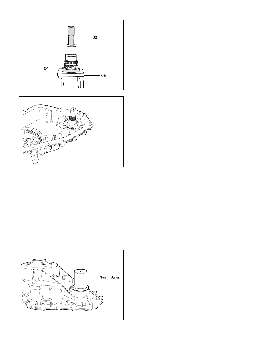
43. If replacement of the needle bearing and bushing

is required, press the bearing and bushing is
required, press the bearing and bushing out as
follows:

Position the input shaft on Axle Bearing/Seal
plate, and using Pinion Bearing Cone Replacer
as a spacer.

Insert Input Shaft Bearing Remover into the input
shaft so it is resting on top of the bearing cage.

Tighten the actuator pin until it stops, then press
the bearing and bushing out together.

YAD5D500

YAD5D510

Assembly Procedure

1. Before assembly, lubricate all parts with Automatic

Transmission Fluid or equivalent.

2. If removed, drive the bearing into the front output

case bore.

Notice: Drive the bearing in straight, making sure
it is not cocked in the bore.

3. Install the internal snap ring that retains the bearing

to the front case.

4. If removed, install the front yoke to flange seal in

the front case bore.

5. If removed, install the yoke to flange seal into the

mounting adapter bore.

YAD5D520

TRANSFER CASE - TOD  5D2-81

SSANGYONG  Y200

YAD5D530

YAD5D540

YAD5D550

YAD5D560

6. If the input shaft needle bearing and bushing were

removed, install a new bearing and bushing as
detailed in the following steps:

Press a new needle bearing, then a new bushing
in the input shaft as follows:

Position the input shaft on Axle Bearing/Seal
Plate or equivalent, and Pinion  Bearing Cone
Replacer as a spacer.

Press a new needle bearing into the end of the
input shaft until it seats in the input shaft.

12. Install the front planet to the sun gear and input

shaft.

13. Install the internal snap ring to the planetary carrier.

7. The recessed face of the sun gear and the snap

ring groove on the bearing outer race should be
toward the rear of the transfer case.

8. The stepped face of the thrust washer should face

toward the bearing.

9. Slide the sun gear, thrust plate and thrust washer

into position on the input shaft.

10. Press the bearing over the input shaft.

11. Install the external snap ring to the input shaft.

Press in a new bushing.

SSANGYONG  Y200

5D2-82  TRANSFER CASE - TOD

YAD5D570

YAD5D580

YAD5D590

YAD5D600

14. Place the tangled snap ring in the case. Expand

snap ring with snap ring pliers and install planetary
carrier assembly. Check installation by holding
the case and carefully tapping the face of the input
shaft against a wooden block to make sure the
snap ring is installed.

15. Remove all traces of gasket sealant from the front

case and mounting adapter mating surfaces.
Install a bead of gasket sealant on the surface of
the front case.

19. Install the output shaft and oil pump in the input

shaft.

Make sure that the internal splines of the ouput
shaft engage the internal splines of the high-low
shift collar.

Make sure that the oil pump retainer arm and oil
filter leg are in the groove and slot of the front case.

18. Inspect the outside surfaces and bore of the oil

pump.

16. Install the high-low shift fork and high-low collar as

an assembly into the front planet.

17. If new pump is used, align the flat of the output

shaft and the flat of the pump. Slide the pump onto
the output shaft.

TRANSFER CASE - TOD  5D2-83

SSANGYONG  Y200

YAD5D610

YAD5D620

YAD5D630

YAD5D640

20. Install the magnet in the slot in the front case just

above the oil filter leg.

21. Install the front output shaft in the front case.

22. Install the thrust washer on the rear output shaft.

26. Install snap ring onto the rear output shaft. Start

the snap ring over the spline and use the wave
spring to seat the snap ring in the snap ring
groove.

If the snap ring will not install, the thrust washer
inside the clutch pack may not be seated properly.

27. Install wave spring, insulator washer and armature.

(Three offset slots must align with housing to be
installed)

Notice: Three slots on the thrust washer must be
aligned with the three tabs on the clutch pack
housing.

24. Install tone wheel onto the front output shaft. Make

sure the spline on the tone wheel engages the
spline on the front output shaft.

25. Install clutch pack assembly onto the rear output

shaft. Make sure the spline of the clutch pack
engages to the spline of the sprocket.

23. Install the chain, drive sprocket and driven

sprocket as an assembly over the output shaft.

Notice: The driven sprocket (on the front output
shaft) must be installed with the marking REAR
facing toward the rear case, if so marked.
Drive sprocket has a bushing pressed into it.


Content   ..  606  607  608  609   ..