SsangYong Stavic / SsangYong Rodius (2005 year). Manual - part 218


  Index      SsangYong     SsangYong Stavic / SsangYong Rodius - service repair manual 2005 year


Search            


Content   ..  216  217  218  219   ..


SsangYong Stavic / SsangYong Rodius (2005 year). Manual - part 218


8

CHANGED BY

EFFECTIVE DATE

AFFECTED VIN

CLUSTER / WARNING & INDICATOR PANEL

STAVIC - 2004.09

2B

(VIN=13 ± 0.1V, Temperature: 25

°C)

Standard speed (Km/h)

Tolerance (Km/h)

20

+4

0

40

+5.5

+2

(60)

+7

+2.5

80

+9

+3.5

100

+10.5

+4

120

+12.5

+6

140

+14.5

+7.5

(160)

+16

+8.5

(180)

+18

+10

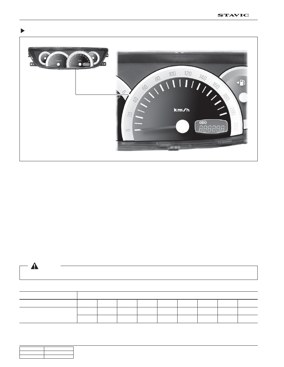
The speedometer indicates the vehicle speed by calculating the signals from the rear right wheel speed sensor through
ABS or ESP unit.

If the speedometer pointer vibrates, stands at a certain range or sounds abnormal noise, there could be defectives in
speedometer. However, these symptoms also could be appeared when the tire has uneven wear, different tire inflation
pressures or different tire specifications.

Perform the speedometer test regarding the tolerance as described. However, it is not similar simple work in field due to
lack of measuring conditions such as test equipment and preciseness.

1. Check the allowable tolerance of the speedometer and operations of the trip odometer by using a tester.

2. Check if the speedometer pointer is shaking and the abnormal noise sounds.

3. Eliminate the hysteresis by tapping the speedometer.

Speedometer

 [Notice]

The allowable tolerance increases when the tires are worn or the tire pressure is out of specified range.

9

CHANGED BY

EFFECTIVE DATE

AFFECTED VIN

CLUSTER / WARNING & INDICATOR PANEL

STAVIC - 2004.09

2B

Fuel Level Gauge

The fuel level gauge displays the resistance value of the float on the fuel sender in the fuel tank through a pointer. Note
that this vehicle doesn’t have a service hole for checking the fuel sender connector in the fuel tank.

The fuel sender and its connector can be checked and replaced only when the fuel tank is removed. The power supply
and resistance value should be measured at the connector in front of the fuel sender (refer to wiring diagram).

When the power supply and output resistance are normal, the float operation by fuel level may be defective; if so, replace
the fuel sender.

Tolerance and resistance value by indicating angle

This table shows the tolerance and resistance value changes by fuel level in normal conditions. Therefore, the differ-
ences that can be occurred by the road conditions and fuel fluctuations are ignored.

Scale

Indicating angle (

°)

Tolerance (

°)

Resistance(

Ω)

Tolerance and resistance value by indicating angle

Full

40

+ 4 ~ 0

38 

±

 1

(3/4)

20

±

 2.5

67 

±

 1

1/2

0

±

 3

99.5 

±

 1

(1/4)

- 20

±

 2.5

247 

±

 1

Full (LFW)

- 40

+ 1.5

260 

±

 1

10

CHANGED BY

EFFECTIVE DATE

AFFECTED VIN

CLUSTER / WARNING & INDICATOR PANEL

STAVIC - 2004.09

2B

Coolant Temperature Gauge

The coolant temperature gauge displays the coolant temperature with a pointer. The angle of pointer that changes by
coolant temperature is as shown below.

0

o

40

o

-40

o

Indicating angle

Tolerance

Coolant temperature

Tolerance and resistance value by indicating angle

- 40 (H)

± 2.5

40

°C

0

°C (1/2)

+0

°C

- 5

°C

70

°C  ~ 110°C

+40(

°C)

+5

°C

+1

°C

Over 125

°C

Measurement of coolant temperature sensor resistance

Measure the resistance between the terminal and the ground with an ohmmeter and replace if the resistance is out
of specified range.

Resistance value by coolant temperature:

20

°C :

2449 

Ω ±5 %

50

°C :

826 

±5 %

80

°C :

321 

±5 %

100

°C :

112 

±5 %

When the resistance value by coolant temperature is within the specified range, check thermostat, water pump, radiator
related coolant circuit for normal operation. Also, check the wiring harnesses and connectors for proper connection.

11

CHANGED BY

EFFECTIVE DATE

AFFECTED VIN

CLUSTER / WARNING & INDICATOR PANEL

STAVIC - 2004.09

2B

TRIP ODOmeter (TRIP A, TRIP B) and ODOmeter

Reset button

* Press and hold (over 1 sec.)

Trip odometer “TRIP A” and “TRIP B” will be reset to 0. (However, only the corresponding driving
range will be set to 0.)

* Press shortly (between 0.1 ~ 1 sec.)

The mode changes in order as shown in the figure.

TRIP A

Displaying range: 0.0 ~ 999.9 km

Increment: 0.1 km

TRIP B

Displaying range: 0.0 ~ 999.9 km

Increment: 0.1 km

ODO

Displaying range: 0 ~ 999999 km

(The odometer stops at 999999 km.)

Increment: 1 km


Content   ..  216  217  218  219   ..