SsangYong Stavic / SsangYong Rodius (2005 year). Manual - part 90


  Index      SsangYong     SsangYong Stavic / SsangYong Rodius - service repair manual 2005 year


Search            


Content   ..  88  89  90  91   ..


SsangYong Stavic / SsangYong Rodius (2005 year). Manual - part 90


DI02-35

CHANGED BY

EFFECTIVE DATE

AFFECTED VIN

ENGINE HOUSING

DI ENG SM - 2004.9

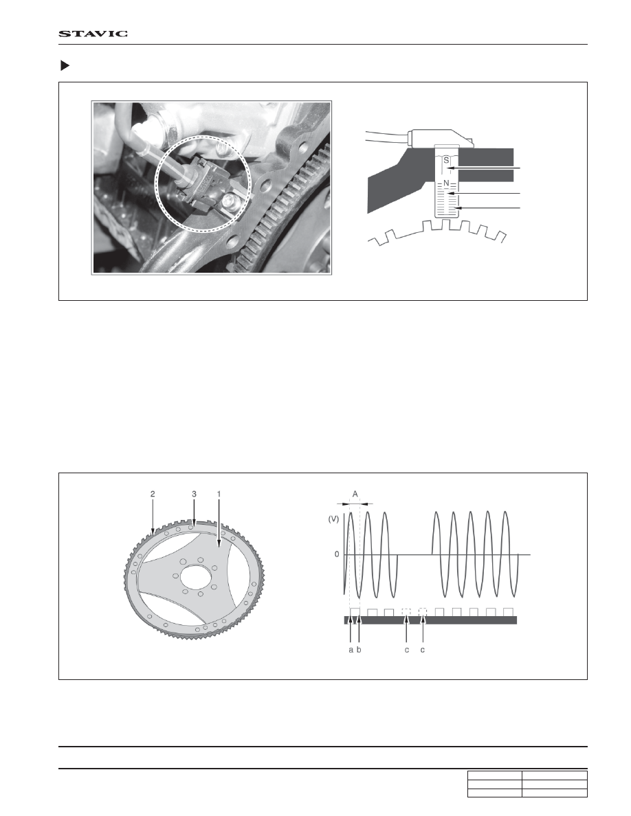
Crankshaft Position Sensor

The crankshaft position sensor is located near to flywheel on the rear of cylinder block. It generates AC voltage between
increment type driven plate that fixed on flywheel inside. The sensor consists of soft iron core that winded copper wire
on permanent magnet and generates sign wave AC voltage when magnetism on the sensor wheel passes the sensor.

When the crankshaft rotates, ‘+’ signal will be generated from near the front edge and ‘-’ signal will be generated from
near the rear edge among teeth on the driven plate near to crankshaft position. The AC voltage increases as the engine
speed increases, however, no signal occurs from the 2-missing-tooth on the increment type driven plate. By using these
teeth, ECU recognizes TDC of No. 1 and 5 cylinders.

ECU converts the alternative signals into digital signals to recognize crankshaft position, piston position and engine
speed. The piston position that coupled with crankshaft is main factor in calculating injection timing. By analyzing the
reference position and camshaft position sensor, can recognize No. 1 cylinder and calculate the crankshaft speed.

A. Distance between ‘+’ max. voltage and ‘-’ max.

voltage

a. Front edge

b. Rear edge

c . 2-missing-tooth

<Location of crankshaft position sensor>

<Drive plate>

<Structure of crankshaft position sensor>

Permanent
magnet

Ring gear

Iron

coil

Standard

position

DI02-36

CHANGED BY

EFFECTIVE DATE

AFFECTED VIN

ENGINE HOUSING

DI ENG SM - 2004.9

<Circuit diagram of crankshaft position sensor>

Output voltage

( 1 ~ 150 V)

Sensor unit coil resistance (

)

Sensor air gap

Operating temperature

Tightening torque

Min. voltage: 1.0 V (40 rpm, air gap: 1.3 mm)

Max voltage: 150 V (7000 rpm, air gap: 0.3 mm)

1,090 ± 15 %

0.3 ~ 1.5 mm

- 40 ~ 150°C

6 ~ 8 Nm

Drive plate

Crankshaft position

sensor

Ground

Signal

DI02-37

CHANGED BY

EFFECTIVE DATE

AFFECTED VIN

ENGINE HOUSING

DI ENG SM - 2004.9

TORSIONAL VIBRATION DAMPER

System Description

• Components: Hub, inertia ring, cover, bearing, bushing, silicone oil

• Functions: The crankshaft pulley optimizes the drive system by reducing the amount of torsional vibration in crankshaft.

Conventional rubber damper is limited in changing materials (rubbers) to absorb vibration, but this crankshaft
pulley (viscous damper), using silicone oil, takes advantage of less changing viscosity according to the
temperature.

Hub

Pin

Silicone oil

Inertia ring

Bushing

Cover

Bearing

Pin

Laser welding

DI02-38

CHANGED BY

EFFECTIVE DATE

AFFECTED VIN

ENGINE HOUSING

DI ENG SM - 2004.9

2. Remove the bearing cap bolts.

3. Remove the bearing caps.

Notice

Position the #1 piston at TDC and remove the piston
connecting rod journal bearing caps.

4. Remove the bearing caps and lower thrust bearing.

5. Separate the lower bearing shells from the bearing caps.

Notice

The crankshaft bearing caps are marked with
stamped numbers. Start to remove from the
crankshaft pulley side.

Do not mix up the bearing shells.

DIASSEMBLY AND REASSEMBLY

1. Unscrew the bolts and remove the connecting rod journal

bearing and bearing caps.

Notice

Do not mix up the bearing shells.

6. Remove the crankshaft.

7. Remove the upper thrust washers.

8. Remove the upper bearing shells from the crankcase.


Content   ..  88  89  90  91   ..