SsangYong Stavic / SsangYong Rodius (2005 year). Manual - part 66


  Index      SsangYong     SsangYong Stavic / SsangYong Rodius - service repair manual 2005 year


Search            


Content   ..  64  65  66  67   ..


SsangYong Stavic / SsangYong Rodius (2005 year). Manual - part 66


1G-13

CHANGED BY

EFFECTIVE DATE

AFFECTED VIN

ENGINE INTAKE & EXHAUST

M162 GSL ENG SM - 2005.7

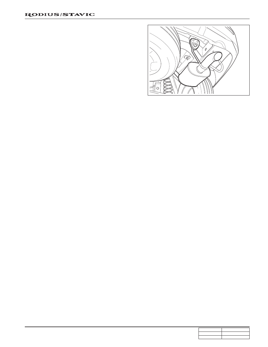
7. Remove the mounting hanger and tail exhaust pipe.

8. Check the muffler and pipes for holes, damage, open

seams, or other deterioration. Which could permit
exhaust fumes to seep into the passenger compartment
or the trunk.

9. Installation should follow the removal procedure in the

reverse order.

1G-14

CHANGED BY

EFFECTIVE DATE

AFFECTED VIN

ENGINE INTAKE & EXHAUST

M162 GSL ENG SM - 2005.7

FASTENER TIGHTENING SPECIFICATIONS

SPECIFICATIONS

Lb-In

-

-

-

-

-

80 ~ 97

Lb-Ft

11 ~ 21

21 ~ 35

16.6 ~ 20.3

16.6 ~ 20.3

21 ~ 35

-

 Nm

15 ~ 28

28 ~ 47

22.5 ~ 27.5

22.5 ~ 27.5

28 ~ 47

9 ~ 11

Application

Exhaust manifold to front exhaust pipe nut

Front exhaust pipe to muffler nut

Intake air duct mounting bolt

Intake manifold mounting bolt

Muffler to tail exhaust pipe nut

Resonance flap mounting bolt

DI0A-1

CHANGED BY

EFFECTIVE DATE

AFFECTED VIN

GENERAL INFORMATION

DI ENG SM - 2004.9

GENERAL INFORMATION

 00

SECTION DI0A

Table of Contents

CLEANNESS ....................................... DI0A-2

STRUCTURE ...................................... DI0A-7

ENGINE CONTROLS ....................... DI0A-10

ECU related components ............. DI0A-10

Engine and sensors ...................... DI0A-11

Electrical components and pre heating
system .......................................... DI0A-12

INTAKE SYSTEM ............................. DI0A-13

Intake air flow chart ...................... DI0A-14

EXHAUST SYSTEM .......................... DI0A-15

Exhaust air flow chart ................... DI0A-16

LUBRICATION SYSTEM .................. DI0A-17

COOLING SYSTEM ......................... DI0A-18

Coolant flow chart ........................ DI0A-19

FUEL SYSTEM ................................. DI0A-20

Fuel supply system ...................... DI0A-21

MAINTENANCE AND REPAIR .......... DI0A-22

Maintenance and lubrication ....... DI0A-22

Guidelines for
service work safety ...................... DI0A-23

Vehicle lifting procedures ............ DI0A-28

OWNER INSPECTIONS AND SERVICES

.......................................................... DI0A-30

While operating the vehicle ......... DI0A-30

At each fuel fill ............................. DI0A-30

At least twice a month .................. DI0A-30

At least monthly ........................... DI0A-30

At least twice a year ..................... DI0A-31

Each time the oil is changed ....... DI0A-31

At least annually .......................... DI0A-31

STANDARD BOLTS SPECIFICATIONS

.......................................................... DI0A-32

BASIC SPECIFICATION ................... DI0A-34

Vehicle specifications ................... DI0A-34

Specifications ............................... DI0A-35

Maintenance ................................ DI0A-37

VEHICLE IDENTIFICATION .............. DI0A-39

Vehicle identification number (VIN)

..................................................... DI0A-39

Manufacturer’s plate .................... DI0A-40

Engine serial number ................... DI0A-40

Transmission & transfer case number

..................................................... DI0A-41

HOW TO USE AND MAINTAIN WORKSHOP
MANUAL ........................................... DI0A-42

Consists of workshop manual ...... DI0A-42

Manual description ...................... DI0A-42

DI0A-2

CHANGED BY

EFFECTIVE DATE

AFFECTED VIN

GENERAL INFORMATION

DI ENG SM - 2004.9

The fuel system for DI engine consists of transfer (low pressure) line and high pressure line. Its highest pressure
reaches over 1600 bar. Some components in injector and HP pump are machined at the micrometer 100 

µm of

preciseness. The pressure regulation and injector operation are done by electric source from engine ECU.
Accordingly, if the internal valve is stucked due to foreign materials, injector remains open. Even in this case, the
HP pump still operates to supply high pressurized fuel. This increases the pressure to combustion chamber (over
250 bar) and may cause fatal damage to engine.

You can compare the thickness of injector nozzle hole and hair as shown in below figure (left side). The right side
figure shows the clearance between internal operating elements.

Cleanness of DI Engine Fuel System and Service Procedures

The core elements of fuel system has very high preciseness that is easily affected by dust or very small foreign
material. Therefore, make sure to keep the preliminary works and job procedures in next pages. If not, lots of
system problems and claims may arise.

CLEANNESS

Hair

Nozzle hole

Valve actuator lift: 0.028 mm

Diameter: 0.40 mm

Operating
clearance:
0.002 mm

Diameter:

2.0 mm


Content   ..  64  65  66  67   ..