SsangYong Musso. Manual - part 494


  Index      SsangYong     SsangYong Musso - service repair manual


Search            


Content   ..  492  493  494  495   ..


SsangYong Musso. Manual - part 494


MANUAL TRANSMISSION  5B-23
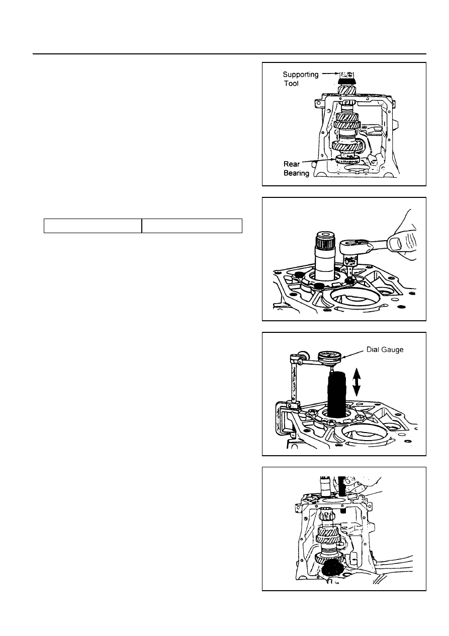
Assembly Procedure

1. Using a hydraulic press and a supporting tool, press the

counter shaft rear bearing into the case. Be sure that the
supporting tool inside of the case should support the counter
shaft.

2. Without the shim, install the retainer and counter shaft rear

bearing outer race. Tighten the 4 retainer bolts.

3. Place a dial indicator on the case and measure counter

shaft end play by moving up and down.

4. Select a shim which is the same thickness as the indicator

rearing (up to 0.004 inch) and assemble it.

5. When the end play is correctly adjusted, remove the counter

shaft rear bearing retainer and outer race.

6. Using a pin punch and rubber hammer, install the reverse

idler shaft, gear and O-ring.

Tightening Torque

20 Nm

5B-24  MANUAL TRANSMISSION

7. Install the counter shaft rear bearing outer race, shim and

retainer.

Tightening Torque

39 - 52 Nm

!

Using a punch and hammer, bend the lock tabs on the

retainer.

8. Install the following parts :

!

Install the main shaft into case.

!

Install the main shaft rear bearing outer race into the

rear of the case.

!

Install the 4th speed blocking ring onto the front of the

main shaft.

!

Install the input shaft onto the front of the main shaft.

!

Install the input bearing retainer without shim onto the

front of the case.

!

Using a torque wrench, tighten the 4 bolts.

9. Install the 5th speed drive gear and blocking ring on the

counter shaft.

10. Install the 5th synchronizer and rail/fork.

11. Install the 5th  synchronizer snap ring and oiling funnel.

12. Align the slots of the lever with the rollers of the reverse

fork and 5th shift rail. Apply sealer on the 5-R lever pivot
bolt and install it into the case.

Tightening Torque

28 Nm

13. Using a needle nose pliers, install the 5-R lever clip.

MANUAL TRANSMISSION  5B-25

14. Using a needle nose pliers, install the reverse fork spring

to its pin inside the case. Check the operation of the 5-R
shift mechanism at this time.

15. Using a snap ring piers, install the slip yoke snap ring onto

the end of the main shaft.

16. Make sure that the 1-2 and 3-4 synchronizer sleeves and

5-R shift lever are in neutral position.

17. Align the holes the case and cover with alignment-type

bolts. Tighten the 10 bolts.

18. Apply ‘RTV’ sealant on the sealing surface of the extension

housing.

19. Apply grease on the detent/guide plate in the extension

housing. Install the detent ball in the 3-4 position.

20. Place the detent spring and offset lever in the extension

housing and push the extension against the case and shift
cover.

5B-26  MANUAL TRANSMISSION

21. Completely compress the detent spring.

22. To install the extension housing to the case, apply sealer

to the top two bolts and tighten them and tighten the 6
bolts.

23. Apply sealer to the back-up lamp switch and drain plug

and tighten them.

24. Using a hammer, install the offset lever-to-shift roll pin.

25. Turn the transmission case reversely and place a dial

indicator on the extension housing. Move the input and
main shift up and down and measure end play. Select a
shim which is the same thickness as the measurement (±
0.001 inch). After shim installation, the end play should be
‘0’.

26. Remove the input bearing retainer and do the following :

!

Install the adjusting shim behind the input bearing outer

race in the retainer and if 2 shims are used, install the
thinner one in first.

!

Install the retainer to the case and tighten the bolts.

!

If end play is not ‘0’change the shim again.

!

Apply RTV sealant to the sealing surface of the retainer.

!

Apply sealer to the 4 retainer bolts and tighten them.

27. Remove the fill plug.

28. Remove the transmission from the holding fixture and install

it to the vehicle.

29. Clean the sealing surface of the shift control lever.

30. Install the control cables to the shift lever.


Content   ..  492  493  494  495   ..