SsangYong Musso. Manual - part 398
1B3-154 OM600 ENGINE MECHANICAL
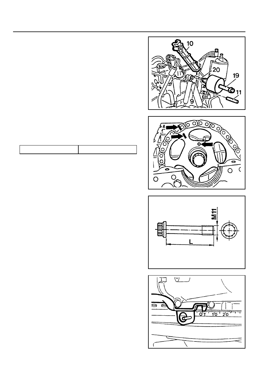
4. Position the no. 1 cylinder at the TDC of OT.
6. Pull out the bearing pins (9, 11) with sliding hammer and
remove the guide rail 10.
Sliding Hammer 116 589 20 33 00
Threaded Pin 116 589 02 34 00
Installation Procedure
1. Apply collar of both bearing pins with sealing compound.
2. Position the guide rail and insert the bearing pins.
3. Install the camshaft sprocket.
Tightening Torque
10 Nm
Notice
If the max. length ‘L’ of the 12-sided bolt exceeds 53.6mm,
replace it.