SsangYong Musso. Manual - part 333


  Index      SsangYong     SsangYong Musso - service repair manual


Search            


Content   ..  331  332  333  334   ..


SsangYong Musso. Manual - part 333


M161 ENGINE CONTROLS  1F2-11

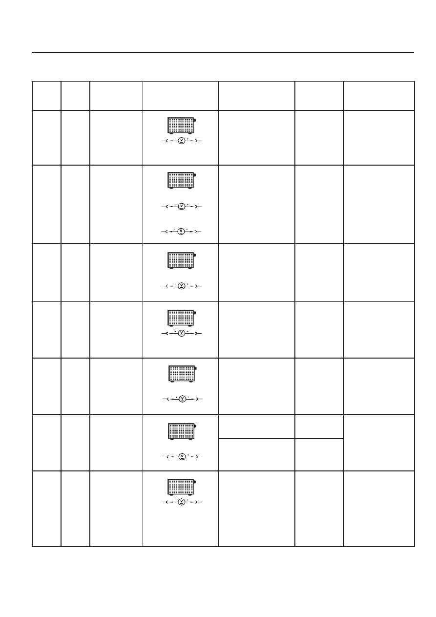
FUEL INJECTION SYSTEM TEST

Failure

code

Item

⇒ 

1.0

Checking method


Ignition:ON

Test

step

Requirement

Specified

value

Possible cause

10

12

11 -14V

•••••

 ECU:power

supply

- terminal 30

(TM.30)

⇒ 

2.2

•••••


Power

supply:

- terminal 87

(TM.87)


Ignition:ON

 Power supply cable

 OVPR

08,

⇒ 

1.1

⇒ 

1.2

⇒ 

1.1

 Ignition:ON

10

2

11 -14V

•••••

 Ground

cable:

- Battery

ground

 Ground cable

 Ground condition

Diagnosis

socket

69

2

Diagnosis

socket

⇒ 

1.2

 Ignition:ON

1

12

11 -14V

•••••

 Power

supply:

- terminal 30

(TM.30)

 Power supply cable

Diagnosis

socket

⇒ 

2.0


Ignition:ON

5

11

11 -14V

•••••

 ECU:power

supply

- terminal 87

(TM.87)

08,

⇒ 

1.1

⇒ 

2.1

⇒ 

2.1


Ignition:ON

11 -14V

•••••

 Ground

cable

- Electronic

ground

 Ground cable

5

2

Diagnosis

socket

1

11

Diagnosis

socket


Ignition:OFF

11 -14V

< 1V

⇒ 

3.0


Engine:in Cranking

5

2


Cable


Ignition Swith

11 -14

(during engine

cranking)

•••••


Start signal:

- terminal 50

(TM.50)

1F2-12  M161 ENGINE CONTROLS

Failure

code

Item

09,

10,

11,

Checking method

Test

step

Requirement

Specified

value

Possible cause

⇒ 

4.0

•••••


HFM sensor

signal

105

81


Ignition:ON

0.9 - 1.1V


 ⇒ 

4.1 - 4.3


Cable


External air inflow


HFM sensor


Engine:in Idle

(Coolant temperature

: > 70

°

C )

1.3 - 1.7V

⇒ 

4.1

105

4


Ignition:ON

 HFM sensor

connector removed

4.7 - 5.2V


Cable


ECU coupling

•••••


HFM sensor:

- 5V power

supply

HFM

sensor

⇒ 

4.2

3

108


Ignition:ON

 HFM sensor

connector removed

4.7 - 5.2V


 ⇒ 

4.3


Cable

•••••


HFM sensor:

- 5V power

supply

HFM

sensor

⇒ 

4.3

104

2


Ignition:ON

 HFM sensor

connector removed

11 - 14V


Cable


OVPR

•••••


HFM sensor:

- 12V power

supply

HFM

sensor

03,

04,

05,

⇒ 

5.0

•••••


Intake air

temperature

sensor:

- Voltage

105

80


Ignition:ON


 ⇒ 

5.1


ECU

⇒ 

5.1


Ignition:OFF

 No.2 ECU coupling

removed

105

80


Cable


HFM sensor

•••••


Intake air

temperature

sensor:

- Resistance

: voltage value

is increased

when engine

rpm is

increased

± 

5%

°

C

10

20

30

40

50

60

± 

5%

3600

2420

1662

1166

853

600

°

C

10

20

30

40

50

60

V

3.1

2.65

2.18

1.76

1.4

1.1

M161 ENGINE CONTROLS  1F2-13

Failure

code

Item

Checking method

Test

step

Requirement

Specified

value

Possible cause

⇒ 

6.1


Ignition:ON

0.1 - 0.3A


Cable


Fuel pump relay


ECU

•••••


Fuel pump

relay:

- Current

consumption

00,

01,

02,

06,

⇒ 

7.0

•••••


Coolant

temperature

sensor:

- Voltage

79

78


Ignition:ON

°

C

V

20

3.57

80

1.22

100

  0.78


 ⇒ 

7.1


ECU

± 

5%

⇒ 

6.0


Ignition:ON

(Fuel pump relay will

operate for 1 - 2

seconds when the

ignition switch is

turned to "ON" after

stopping the

engine)


Engine:cranking

33

11


Cable


Fuel pump relay


ECU

•••••


Fuel pump

relay:

- Operation

34,

35,

11 - 14V

(approx.1-

2sec.)

11 - 14V

(Cranking or

driving)

5

33

⇒ 

7.1


Ignition:OFF

(Remove the No.2

coupling from ECU)

79

78


⇒ 

7.2


cable

•••••


Coolant

temperature

sensor:

- Resistance

& cable

°

C

20        2500

80

322

100

185

± 

5%

⇒ 

7.2

•••••


Coolant

temperature

sensor:

- Resistance

Coolant temperature

sensor:

1

4

 Remove the

connector from

coolant temperature

sensor and measure

the resistance

between No.1 and

No.2 pin with

multimeter.


 refer to

specified

resistance

value of 7.1.


Coolant

temperature

sensor

1F2-14  M161 ENGINE CONTROLS

Failure

code

Item

Checking method

Test

step

Requirement

Specified

value

Possible cause

⇒ 

9.0

 Keep the engine run

above 2 minutes in

over 80

°

C of coolant

temperature

6.0 - 7.0 V


ECU


Cable


Oxygen sensor

•••••


Oxygen

sensor:

- Signal

80,

81,

82,

83,

89,

5

60

⇒ 

8.0

 Engine:in cranking

or idle

5

60


Cable


ECU

•••••


ECU:

- RPM signal

output

32,

33,

refer to figure

2

⇒ 

10.0

 Keep the engine run

above 2 minutes in

over 80

°

C of coolant

temperature.

•••••


Oxygen

sensor:

- Heating

function

operated

⇒ 

11.0

•••••


No.1

cylinder

injector:

- Operating &

injection

time

 When the coolant

temperature is

approx. 20

°

C:

- Engine:in cranking

8.0 ms


Cable


ECU


No.1 Injector


Coolant

temperature sensor


Oxygen sensor


Intake air

temperature sensor

- Voltage

 Engine:in cranking

or idle

(above 5V in idling)

16

17

5

9

9

11


Ignition:ON

11 - 14 V


ECU


Cable


Oxygen sensor

- Current

consumption

0.2 - 2.0 A

72,

73,

63

11

 When the coolant

temperature is

approx. 80

°

C:

- Engine:at idling

speed

- Engine:at sharp

acceleration(full

throttle)

  (refer to figure 3

and 4)

approx.

2.7 - 5.0ms

approx.14ms

There will be a

voltage

fluctuation in

the range of

- 0.2 -1.0V.

85,

86,

87,


Content   ..  331  332  333  334   ..