SsangYong Musso. Manual - part 328


  Index      SsangYong     SsangYong Musso - service repair manual


Search            


Content   ..  326  327  328  329   ..


SsangYong Musso. Manual - part 328


1F1-70  M162 ENGINE CONTROLS
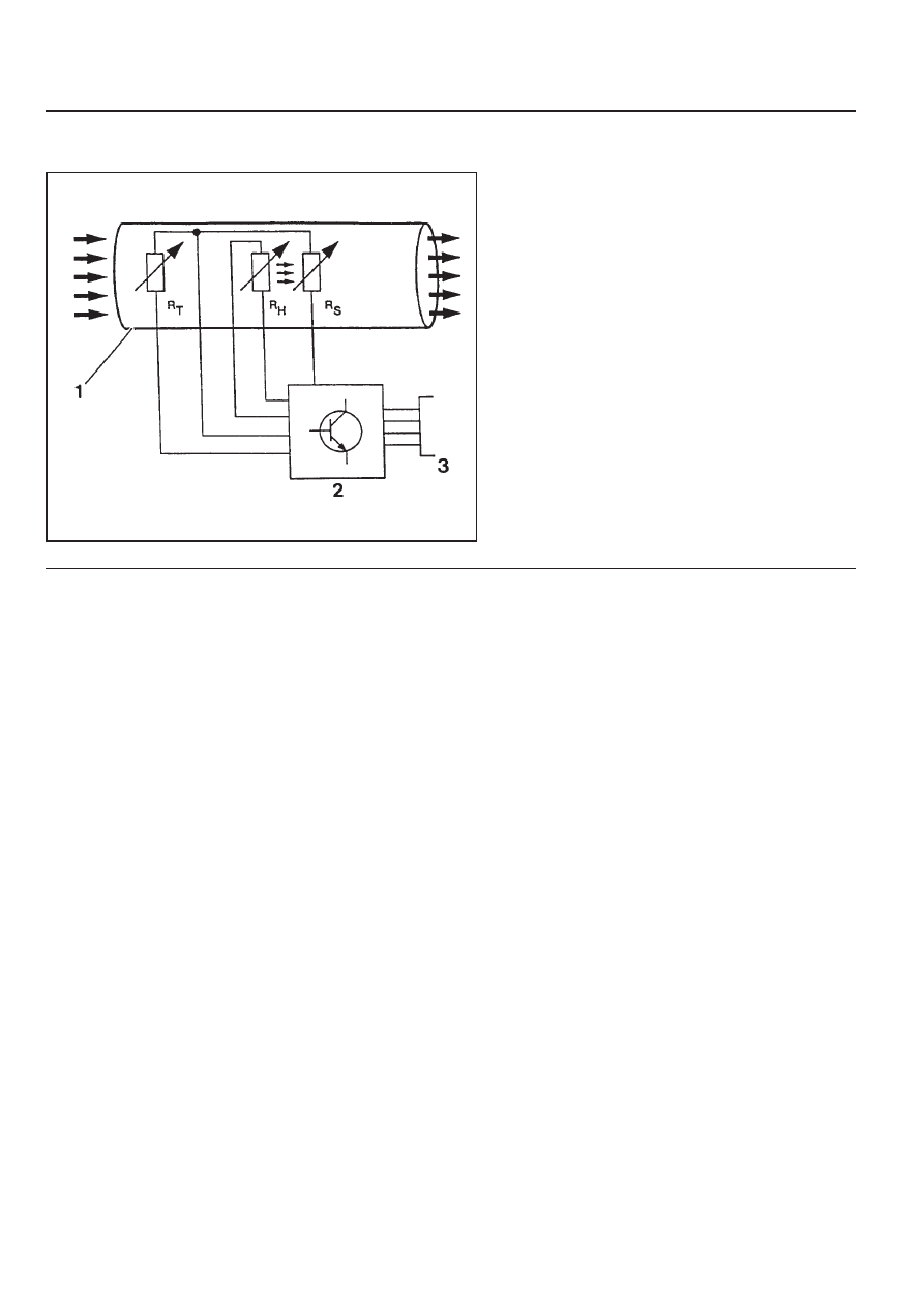
Circuit Diagram

1 Housing
2 Electronic Housing
3 Connector

R

H

 : Heat Resistance

R

T

 : Temperature Resistance

R

S

 : Sensor Resistance

M162 ENGINE CONTROLS  1F1-71

If the measured value is not within the specified value, the
possible cause may be in cable or HFM sensor in itself.
Perform the 5V power supply inspection procedures.

HFM Sensor 5V Power Supply Inspection

1. Measure the voltage between the HFM sensor No.108

(+) and

No.105(-) after removing the HFM sensor connector.

HFM Sensor Input Voltage Inspection

1. Measure the HFM sensor signal voltage between the ECU

terminal No.103 and No.104.

Specified Value (coolant temperature is over 70°C)

If the measured value is not within the specified value, the
possible cause may be in cable or ECU coupling.

Iginition"ON”

0.9 - 1.1 V

Engine at Idle

1.3 - 1.7 V

Specified Value

4.7 - 5.2 V

2. Measure the voltage between the HFM sensor wining

connector terminal No.3 pin(-) and No.4 after removing the
HFM sensor connector.

Specified Value

If the measured value is not within the specified value, the
possible cause may be in cable or over voltage protection
relay.

Perfrom the 12V power supple inspection procedures.

Specified Value

4.7 - 5.2 V

HFM Sensor 12V Power Supply Inspection

1. Measure the voltage between the HFM sensor wiring

connector 1G No.2 pin(+) and No.104 after removing the
HFM sensor connector.

If the measured value is not within the specified value, the
possible cause may be in cable or over voltage protection
relay.

Specified Value

11 - 14 V

1F1-72  M162 ENGINE CONTROLS

OXYGEN SENSOR

1 Electricity Wire
2 Oxygen Sensor Housing
3 Sensor Ceramic
4 Electrode (Internal)
5 Electrode (External)
6 Heating Coil
7 Open Space
8 Protector Tube

Functions

The oxygen sensor optimizes the combustion (Air-Fuel Ratio
14.7:1) and resets the Air-fuel ratio in the ECU after sensing
the amount of oxygen from the exhaust gases to diminish the
exhaust gases.

-

Rich(<1) above approx. 450mV

-

Lean(>1) below approx. 450mV

Locatoin of Sensor

Oxygen sensor is located on the front exhaust pipe.

M162 ENGINE CONTROLS  1F1-73

Oxygen Sensor Signal Voltage Inspection

1. Measure the oxygen sensor signal voltage between the ECU

terminal No.11 and No.9. Maintain the engine speed ia at
idle while the coolant temperature is over 80°C.

If the measured value is not within the specified value, the
possible cause may be in cable, oxygen sensor or ECU.

Oxygen Sensor Heating Voltage Inspection

1. Measure the oxygen sensor heating voltage between the

ECU terminal No.11 and No.9. Maintain the engine speed ia
at idle while the coolant temperature is over 80°C.

If the measured value is not within the specified value, the
possible cause may be in cable, oxygen sensor or ECU.

Oxygen Sensor Heating Current  Consumption
Inspection

1. Measure the oxygen sensor heating current consumption

between the ECU terminal No.9 and No.5 while the ignition
switch is in "ON" position.

If the measured value is not within the specified value, the
possible cause may be in cable, oxygen sensor or ECU.

Specified Value

0.2 - 2.0 A

Specified Value

-0.2 - 1.0 V

Specified Value

11 - 14


Content   ..  326  327  328  329   ..