SsangYong Musso. Manual - part 278


  Index      SsangYong     SsangYong Musso - service repair manual


Search            


Content   ..  276  277  278  279   ..


SsangYong Musso. Manual - part 278


M161 ENGINE MECHANICAL  1B2-39
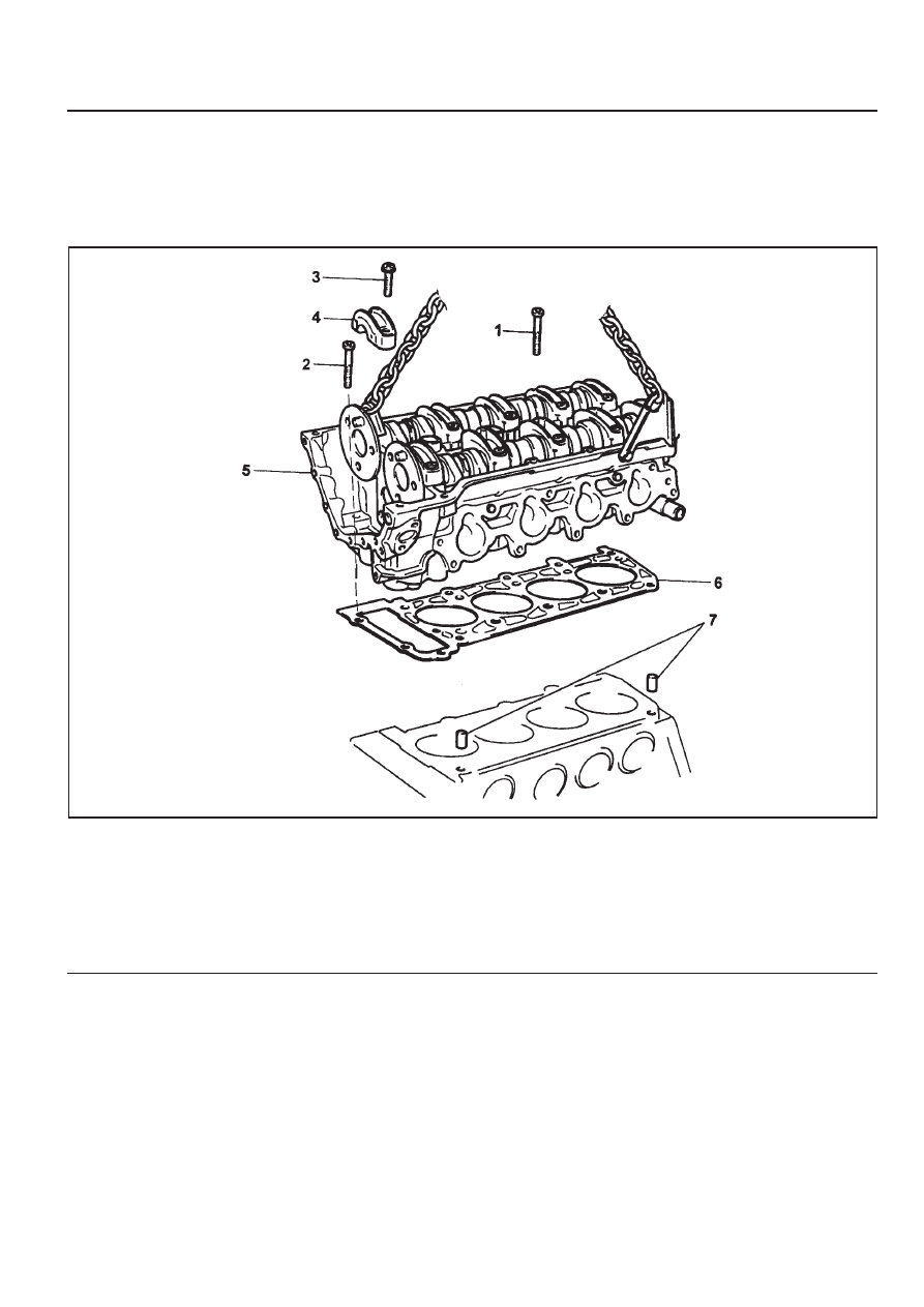
CYLINDER HEAD

Preceding Work : Removal of cylinder head cover

Removal of cylinder head front cover
Removal of intake manifold
Removal of cylinder head lower line (intake manifold side)

1 Cylinder Head Bolt (M12 X 100, 10 pieces)

.................................................... 1st step 55 Nm

2nd step 90° rotation added

3rd step 90° rotation added

3 Bolt (M8 X 35, 4 pieces) ................. 22.5-27.5 Nm

4 Camshaft Bearing cap ................... 22.5-27.5 Nm
5 Cylinder Head
6 Gasket ................................................... Replace
7 Dowel Sleeve ............................................... Note

1B2-40  M161 ENGINE MECHANICAL

Tools Required

617 589 00 10 00  Wrench Socket

116 589 20 33 00  Sliding Hammer

116 589 01 34 00  Threaded Bolt

001 589 66 21 00  Torque Wrence

104 589 00 40 00  Holder

Removal & Installation Procedure

1. Rotate the crankshaft so that the piston of number 1 cylinder

is at ATDC 20.

2. Put the pin into the camshaft bearing cap (number 1, 6).

Pin 111 589 03 15 00

3. Put the alignment marks (arrows) on the timing chain and

camshaft sprocket.

4. Remove the chain tensioner.

Installation Notice

Tightening  Torque

72 - 88 Nm

Tightening Torque

1st step 18 - 22 Nm

2nd step 85° - 95°

5. Remove the exhaust camshaft sprocket.

Installation Notice

Notice

The flange bolt is designed to be used only once, so always
replace with new one.

M161 ENGINE MECHANICAL  1B2-41

6. Remove the in take camshaft sprocket (E20 engine).

7. Remove the camshaft adjuster (E23, M161.970 engine).

Installation Notice (Flange Bolt)

1

Flange Shaft

2

Flange Bolt

3

Campression Spring

4

Adjust Piston

5

Camshaft Sprocket

6

Seal Cover

7

Nut

Tightening Torque

1st step 18 - 22 Nm

2nd step  85° - 95°

Notice

The flange bolt is designed to be used only once, so always
replace with new one.

8. Remove the guide rail pin using the sliding hammer (02)

and the threaded pin (03).

Notice

Apply the sealant on guide rail pin when installation.

9. Unscrew the bolts (A).

Installation Notice

Tightening Torque

22.5 - 27.5 Nm

Bolt (A) : (M8 X 35, 4 pieces)

1B2-42  M161 ENGINE MECHANICAL

10. Remove the cylinder head bolts in the reverse order of

the numerics (No.10 

 No.1).

Installation Notice

Tighten the bolts as numerical order with specified torque

(No.1 

 No.10).

Holder 104 589 00 40 00

1

Cylinder Head Bolt

2

M8 X 35 Bolt & Washer

3

Bearing Cap

4

Engine Hoist

5

Gasket

6

Hanger Bracket

Tightening Torque

1st step 55  ± 5 Nm

2nd step + 90°

3rd step + 90°

11. Remove the No. 1 bearing cap of the exhaust camshaft.

Installation Notice

Tightening  Torque

22.5 - 27.5 Nm

12. Install the special tool (05) on the bearing cap removed

place and hook the engine hoist into them and remove
the cylinder head carefully.

13. Check the cylinder head mating surface and clean the

crankcase head bolt mounting hole.

14. Replace the cylind head gasket with new one.

Notice

Operate during engine cooling.


Content   ..  276  277  278  279   ..