SsangYong Musso. Manual - part 211


  Index      SsangYong     SsangYong Musso - service repair manual


Search            


Content   ..  209  210  211  212   ..


SsangYong Musso. Manual - part 211


1F-428  ENGINE CONTROLS

SSANGYONG  Y158

KAA1F760

KAA1F750

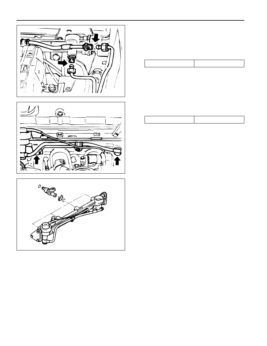
7. Remove the fuel return and supply line.

Notice: For removal, cover around parts with cloths not to
be stained by fuel. In case of checking the injector only,
do not remove the fuel return and supply line.

Installation Notice

8. Remove the for injector connectors.

Notice:  Before removal, the fuel rail assembly may be
cleaned with a spray-type cleaner, following package
instructions. Do not immerse the fuel rails in liquid cleaning
solvent. Use care in removing the fuel rail assembly to
prevent damage to the electrical connectors and injector
spray tips. Prevent dire and other contaminants from
entering open lines and passages. Fittings should be
capped and holes plugged during service
Important:  If an injection becomes separated from the
rail and remains the cylinder head, replace the injector O-
ring seals and the retaining clip.

10. Remove the injectors and the fuel rail carefully.

11. Remove the fuel injector retainer clips.

12. Remove the fuel injectors by pulling them down and

out.

13. Discard the fuel injector O-rings.

14. Lubricate the new fuel injector O-ring with engine

oil. Install the new O-ring on the fuel injectors.

15. Perform a leak check of the fuel rail and fuel

injectors.

16. Installation should follow the removal procedure in

the reverse order.

9. Remove the two combination bolts.

Installation Notice

Tightening Torque

25 N•m (18 lb-ft)

Tightening Torque

25 N•m (18 lb-ft)

KAA1F750

KAA1F760

KAA1F770

ENGINE CONTROLS  1F-429

SSANGYONG  Y158

KAA1F070

KAA1F060

KAA1F440

9. Remove the fuel return and supply line.

Notice: For removal, cover around parts with cloths not to
be stained by fuel. In case of checking the injector only,
do not remove the fuel return and supply line.

Installation Notice

10. Remove the six injector connectors.

FUEL RAIL AND INJECTORS
(3.2L DOHC)

Removal and Installation Procedure

Caution: The fuel system is under pressure. To avoid
fuel spillage and the risk of personal injury or fire, it
is necessary to relieve the fuel system pressure
before disconnecting the fuel lines.

1. Discharge the fuel pressure from the fuel pressure

test connector.

2. Disconnect the negative cable.

3. Disconnect the vacuum hose from the fuel pressure

regulator.

4. Remove the cable guide.

5. Disconnect the Hot Film Air Mass (HFM) sensor

connector.

6. Remove the intake air duct mounting bolts.

Installation Notice

7. Remove the intake air duct clamps.

8. Remove the intake air duct.

Tightening Torque

9 N•m (80 lb-in)

Tightening Torque

25 N•m (18 lb-ft)

KAA1F440

KAA1F060

KAA1F070

11. Remove the two left and two right bolts and one

center bolt of the fuel rail assembly from the intake
manifold.

Installation Notice

Tightening Torque

25 N•m (18 lb-ft)

KAA1F080

1F-430  ENGINE CONTROLS

SSANGYONG  Y158

KAA1F090

Notice:  Before removal, the fuel rail assembly may be
cleaned with a spray-type cleaner, following package
instructions. Do not immerse the fuel rails in liquid cleaning
solvent. Use care in removing the fuel rail assembly to
prevent damage to the electrical connectors and injector
spray tips. Prevent dire and other contaminants from
entering open lines and passages. Fittings should be
capped and holes plugged during service
Important:  If an injection becomes separated from the
rail and remains the cylinder head, replace the injector O-
ring seals and the retaining clip.

12. Remove the injectors and the fuel rail carefully.

13. Remove the fuel injector retainer clips.

14. Remove the fuel injectors by pulling them down and

out.

15. Discard the fuel injector O-rings.

16. Lubricate the new fuel injector O-ring with engine

oil. Install the new O-ring on the fuel injectors.

17. Perform a leak check of the fuel rail and fuel

injectors.

18. Installation should follow the removal procedure in

the reverse order.

ENGINE COOLANT
TRMPERATURE SENSOR
(2.3L DOHC)

Removal and Installation Procedure

1. Relieve the coolant system pressure.

2. Disconnect the negative battery cable.

3. Remove the protection cover.

4. Disconnect the Engine Coolant Temperature (ECT)

sensor connector.

KAA1F090

KAA1F780

Notice: Take care when handling the ETC sensor. Damage
to the sensor will affect the proper operation of the fuel
injection system.

5. Remove the ECT sensor.

Installation Notice

6. Installation should follow the removal procedure in

the reverse order.

Tightening Torque

30 N•m (22 lb-ft)

ENGINE CONTROLS  1F-431

SSANGYONG  Y158

KAC1F240

KAC1F250

ENGINE COOLANT
TRMPERATURE SENSOR
(3.2L DOHC)

Removal and Installation Procedure

1. Relieve the coolant system pressure.

2. Disconnect the negative battery cable.

3. Disconnect the Engine Coolant Temperature (ECT)

sensor connector.

Notice: Take care when handling the ETC sensor. Damage
to the sensor will affect the proper operation of the fuel
injection system.

4. Remove the ECT sensor.

Installation Notice

5. Installation should follow the removal procedure in

the reverse order.

THROTTLE BODY (INTEGRATED
WITH THE ACTUATOR)
(2.3L DOHC)

Removal and Installation Procedure

1. Disconnect the negative batterry cable.

2. Disconnect Intake Air Temperature (IAT) sensor

connector.

3. Remove the intake air duck clamps.

Tightening Torque

30 N•m (22 lb-ft)

YAA1F150

KAC1F250

4. Remove the blow-by hose.

5. Remove the intake air duck.

KAC1F240


Content   ..  209  210  211  212   ..