SsangYong Musso. Manual - part 121


  Index      SsangYong     SsangYong Musso - service repair manual


Search            


Content   ..  119  120  121  122   ..


SsangYong Musso. Manual - part 121


1F-68  ENGINE CONTROLS

SSANGYONG  Y158

29

Check for an open wire between the cooling fan relay
(LH high) connector terminal 30 and engine fuse block
fuse Ef5 and repair as necessary.
Is the repair complete?
1. Turn the ignition OFF.
2. Replace the cooling fan relay (LH high).
Is the action complete?
Replace the cooling fan motor (LH).
Is the action complete?
1. Turn the ignition OFF.
2. Disconnect the cooling fan relay (RH low) connector.
3. Start the engine.
4. Turn the A/C switch ON.
5. With a test light connected to battery, probe the

cooling fan relay (RH low) connector terminal 85.

Is the test light ON?
With a test light connected to battery, probe the cooling
fan relay (RH low) connector terminal 87.
Is the test light ON?
With a test light connected to ground, probe the cooling
fan relay (RH low) connector terminal 86.
Is the test light ON?
With a test light connected to ground, probe the cooling
fan relay (RH low) connector terminal 30.
Is the test light ON?
1. Turn the ignition OFF.
2. Replace the cooling fan relay (RH low)
Is the action complete?
Check for an open wire between the cooling fan relay
(RH low) connector terminal 85 and FATC controller
terminal A16 (or Manual A/C controller terminal 1) and
repair as necessary.
Is the repair complete?
Check for an open wire between the cooling fan relay
(RH low) connector terminal 87 and the cooling fan relay
(RH high) connector terminal 87 and repair as neces-
sary.
Is the repair complete?
Check for an open wire between the cooling fan relay
(RH low) connector terminal 86 and I/P fuse block fuse
F19 and repair as necessary.
Is the repair complete?
Check for an open wire between the cooling fan relay
(RH low) connector terminal 30 and engine fuse block
fuse Ef5 and repair as necessary.
Is the repair complete?

Step

Action

Value(s)

Yes

No

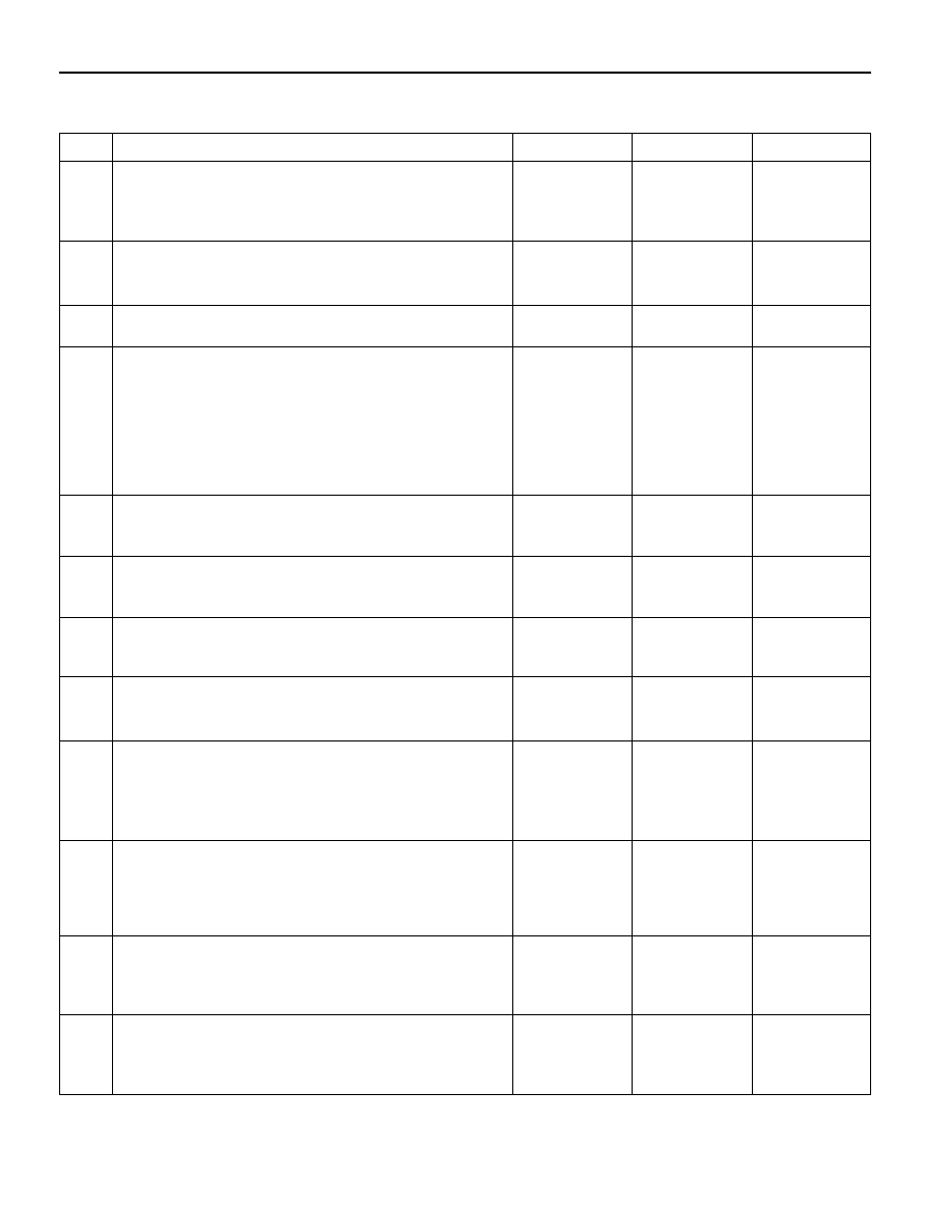
Engine Cooling Fan Circuit Check -  with A/C (Cont’d)

-

System OK

-

30

31

34

-

 Go to Step 33

 Go to Step 38

32

-

 Go to Step 35

 Go to Step 39

35

-

 Go to Step 36

 Go to Step 40

36

-

 Go to Step 37

 Go to Step 41

38

-

System OK

Go to “7B or

7D section”

39

-

System OK

-

40

-

System OK

-

41

-

System OK

-

-

System OK

-

-

System OK

-

37

-

System OK

-

ENGINE CONTROLS  1F-69

SSANGYONG  Y158

BLANK

1F-70  ENGINE CONTROLS

SSANGYONG  Y158

Circuit Description

The provision for communicating with the Engine Con-
trol Module (ECM) is the Data Link Connector (DLC). It
is located under the instrument panel. The DLC is used
to connect the scan tool. Battery power and ground is
supplied for the scan tool through the DLC. The serial
data circuit to the DLC allows the ECM to communicate
with the scan tool. Also DLC provides serial data line to
communicate with the other modules such as the Elec-
tronic Brake Control Module (EBCM), the Transmission
Control Module.

Diagnostic Aids

Ensure that the correct application (model line, car year,
etc.) has been selected on the scan tool. If communica-
tion  still cannot be established, try the scan tool on
another vehicle to ensure that the scan tool or cables
are not the cause of the condition.

An intermittent may be caused by a poor connection,
rubbed through wire insulation, or a broken wire inside
the insulation.

Any circuitry that is suspected of causing an intermittent
complaint should be thoroughly checked for the follow-
ing conditions:

•••••

Backed-out terminals.

•••••

Improper mating of terminals.

•••••

Broken locks.

DATA LINK CONNECTOR DIAGNOSIS

•••••

Improperly formed or damaged terminals.

•••••

Poor terminal-to-wiring connection.

•••••

Physical damage to the wiring harness.

•••••

Corrosion.

Test Description

Number(s) below refer to the step(s) number on the
Diagnostic Table.

1. The Euro On-Board Diagnostic (EOBD) System

Check prompts the technician to complete some
basic checks and store the freeze frame and failure
records data on the scan tool if applicable. This
creates an electronic copy of the data taken when
the malfunction occurred. The information is then
stored on the scan tool for later reference.

8. Locate and repair any shorts that may have caused

the fuse to open before replacement, if the no volt-
age condition was due to an open fuse.

11. The replacement ECM must be reprogrammed. Re-

fer to the latest Techline procedure for ECM repro-
gramming.

16. The scan tool or associated cables could be mal-

functioning. Refer to the scan tool’s manual for re-
pair information.

YAA1F84A

ENGINE CONTROLS  1F-71

SSANGYONG  Y158

1

Perform an Euro On-Board Diagnostic (EOBD) System
Check.
Is the check performed?

1. Turn the ignition ON, with the engine OFF.
2. Install the scan tool.
Does the scan tool power up?
1. Disconnect the scan tool.
2. With a test light connected to ground, probe the

serial data terminal 7 at the Data Link Connector
(DLC).

Does the test light remain OFF?
1. Disconnect the scan tool.
2. With the test light connected to ground, probe the

DLC battery feed circuit terminal 16.

Does the test light illuminate?
With the test light connected to B+, probe the serial
data terminal 7 at the DLC.
Does the test light remain OFF?
Check the serial data circuit for a short to voltage and
repair as necessary.
Is a repair necessary?
With the test light connected to B+, probe the DLC
ground circuit terminal 4 and 5.
Does the test light illuminate for both circuits?
Repair the open or short to ground in the DLC battery
feed circuit.
Is the repair complete?
Check the serial data circuit for an open or poor
connection and repair as necessary.
Is a repair necessary?
Check the serial data circuit for short to ground and
repair as necessary.
Is a repair necessary?
1. Turn the ignition OFF.
2. Replace the ECM.
Is the repair complete?
Repair the open or poor connection(s) in the DLC
ground circuit(s).
Is the repair complete?
Install the scan tool.
Can the scan tool communicate with the ECM?
Install the scan tool on another vehicle with a serial data
terminal and check for proper operation.
Does the scan tool work properly on a different vehicle?
Check the DLC electrical terminals for proper tension or
excessive resistance and repair as necessary.
Is a repair necessary?

Step

Action

Value(s)

Yes

No

Data Link Connector Diagnosis

-

 Go to Step 2

Go to “Euro

On-Board

Diagnostic

System Check”

2

3

4

9

-

 Go to Step 3

 Go to Step 4

-

 Go to Step 5

 Go to Step 6

-

 Go to Step 9

 Go to Step 10

-

 Go to Step 17

 Go to Step 11

-

 Go to Step 15

 Go to Step 12

-

 Go to Step 17

-

-

 Go to Step 17

 Go to Step 13

-

 Go to Step 17

 Go to Step 11

-

 Go to Step 17

-

5

6

7

8

10

11

-

 Go to Step 7

 Go to Step 8

12

13

-

 Go to Step 11

 Go to Step 16

14

-

 Go to Step 17

-

-

 Go to Step 17

 Go to Step 14

-

 Go to Step 17

 Go to Step 16

15


Content   ..  119  120  121  122   ..