SsangYong Musso. Manual - part 2


  Index      SsangYong     SsangYong Musso - service repair manual


Search            


Content   ..  1  2  3   ..


SsangYong Musso. Manual - part 2


MUSSO-SPORTS  1A-5

SUPPLEMENT

KAA5A020

KAA5A020

KAA5A020

EGR Valve and Lift Sensor

1. EGR valve: The output signals from EGR unit controls

the vacuum modulator 1 through step 1 to step 16
precisely, accordingly the opening value of EGR valve
will be changed.

2. Lift sensor (potentiometer): EGR unit converts the

position of EGR valve into electrical signal to detect
the opening value of the valve (Lift sensor). In addition
to, this compensates the opening value of EGR valve
by controlling the vacuum modulator 1 when there
are some differences between the output signal from
vacuum modulator 1 and the input value of
potentiometer from EGR valve.

If the closing or opening value EGR valve is different
from the output value due to the carbon and paticle
material in exhaust gas, the opening value of EGR
valve is compensated by adjusted the vacuum level
of vacuum modulator.

Measured EGR valve opening value

Step

1

2

Vacuum

(mbar)

approx. -370

approx. -690

Valve opening

value (mm)

approx. 0.2

approx. 6.0

Output

voltage (V)

approx. 1.7 ~ 2.1

approx. 9.6 ~ 11.6

1. The opening value of the valve is the internal moving

distance of EGR valve by vacuum pressure. The
valve starts to move when the vacuum pressure
reaches approximately -370 mbar. If the EGR valve
is fully opened, the moving distance will be 6 mm
due to -690 hpa of vacuum pressure.

2. The output voltage may vary according to the battery

voltage in vehicles. These values have been converted
into percentage from battery voltage in each step.

•••••

Step 1: 15% of battery voltage

•••••

Step 2: 64% of battery voltage

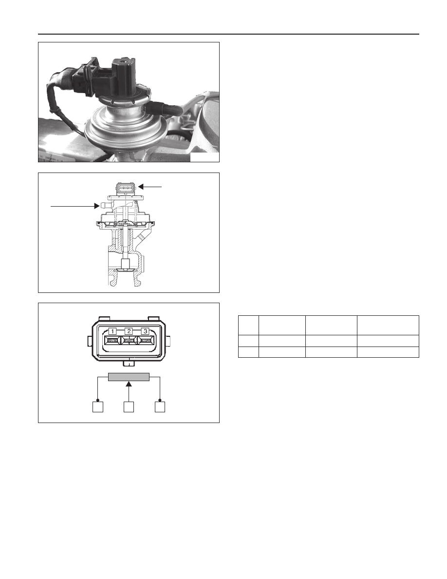
Location of EGR valve

EGR valve arrangement

Vacuum
modulator 1

Connector
(potentiometer)

Circuit of potentiometer

3

1

2

1A-6  MUSSO-SPORTS

SUPPLEMENT

Coolant Temperature Sensor (CTS)

1. Location: on cylinder block

2. Coolant temperature MAP (4 Stages)

T0: 10 ~ 24 °C

T1: 25 ~ 40 °C

T2: 41 ~ 61 °C

T3: above 61 °C

3. If the EGR system is normally defective while engine

is cold (or during warming up), it may be caused by
incorrect input signal of the coolant temperature
sensor.

4. Resistance between pin 1 and pin 4 of the connector

20 °C: 2250 ± 159.0 

50 °C: 836 ± 41.5 

80 °C: 321 ± 15.0 

120 °C: 113 ± 7.2 

KAA5A040

KAA5A060

KAA5A060

Solenoid Valve

1. This valve is used in no-load sharp acceleration mode.

2. Solenoid valve (Normal Open type)

•••••

Normal: Solenoid valve opens, then intake
manifold pressure will operate ALDA.

•••••

No-load sharp acceleration mode: Solenoid valve
closes, then vacuum pressure operate ALDA.

3. Operating voltage: approx. 12 V

4. Resistance: approx. 22.4 ± 1.4 

5. Check the connections in each passage when

supplying or cutting off the operating voltage.

The valve passage to ALDA will be changed when the
battery voltage is supplied through EGR control unit.

Changed to ALDA (1 to 3) or vacuum from intake manifold

Changed to ALDA (2 to 3) from modulator 2

(Refer to exhaust gas control mode with no-load sharp
acceleration)

TPS sensor

Solenoid valve

Intake manifold

ALDA

EGR control unit

3

1

2

Vacuum modulator 2

2

1

3

300

OHM

+

-

MUSSO-SPORTS  1A-7

SUPPLEMENT

Throttle Position Sensor (TPS)

1. EGR unit receives TPS signal from TCU (A/T) or input

signal from pin 61 of EGR unit (M/T). The load value
of engine is important signal because Huber EGR
system make EGR valve operate in extended range
except no-load sharp acceleration mode.

2. Resistance check

•••••

Disconnect the TPS sensor connector from fuel
injection pump and measure the entire resistance
between pin 1 and pin 4.

Specified value: 5 k

 ± 20 %

•••••

Measure the resistance between pin 1 and pin 2
at no-load and full-load.

Approx. 10 ~ 20 % of full resistance at no-load

Approx. 70 ~ 85 % of full resistance at full-load

3. Voltage check

•••••

The supplied voltage to TPS from EGR unit (for
M/T) or TCU (for A/T) is approx. 5 V.

0.60 ± 0.2 V at no-load

3.85 ± 0.3 V at full-load

VACUUM LINE

Installation of modulator and vacuum line (on-vehicle)

EGR 진공모듈레이터1

(열림량 제어)

F/A 제어 진공모듈레이

(열림량 제어)

F/A 제어 솔레노이드밸브

(ON/OFF제어)

TPS 센서

KAA5A060

EGR vacuum modulator 1

(opening value control)

F/A control vacuum modulator

(opening value control)

TPS sensor

F/A control solenoid valve

(ON/OFF control)

1A-8  MUSSO-SPORTS

SUPPLEMENT

MAINTENANCE AND REPAIR

VACUUM PUMP AND VACUUM LINE

This diagnosis procedure checks for vacuum leaks and actuator's operation while performing the actual control of
EGR unit through vacuum lines in vacuum pump. The following special service tools should be used for this procedure.

001 589 73 21 00

Manual Vacuum Pump

Multi-Tester

201 589 13 21 00

Vacuum Tester

KAA5A2P0

KAA5A2R0

KAA5A2Q0

VACUUM LINE TEST

Check the EGR system when the vehicle produces
excessive exhaust gas.

Check the vacuum lines for leaks and blocks.

If there are not any faults, check the actuators controlled
by EGR control unit.

Install the tester in position according to the vacuum
circuit diagram.

To prevent personal injury, beware of moving parts of
engine.


Content   ..  1  2  3   ..