Skoda Rapid (2019 year). Manual - part 5


  Index      Skoda     Skoda Rapid (2019 year) - manual in english


Search            copyright infringement  


Content      ..     3      4      5      6     ..


Skoda Rapid (2019 year). Manual - part 5


Clothes hook

Fig. 89 

Clothes hooks

Read and observe   and   on page 71 first.

The clothes hooks are located on the middle door pillars of the vehicle and on

the handle of the headliner above each of the rear doors 

» Fig. 89

.

The maximum permissible load of each of the hooks is 2 kg.

WARNING

Never leave any heavy or sharp-edged objects in the pockets of the items

of clothing hung up - danger of injury.

Do not use hangers to hang up the clothes - there is a risk of restricting

the effectiveness of head airbags and a danger of injury from the hanger.

Make sure that any clothes hanging from the hooks do not impede your

vision.

Storage pockets on the backs of the front seats

Fig. 90 

Map pockets

Read and observe   and   on page 71 first.

The map pockets are intended for storage of maps, magazines, etc.

Storage pockets on the inner sides of the front seats
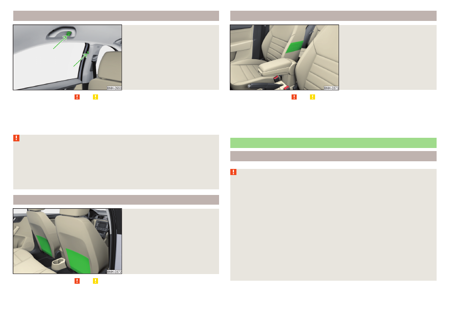
Fig. 91 

Storage pocket

Read and observe   and   on page 71 first.

The storage pockets are located on the inside of the front seats 

» Fig. 91

 and

are used to store small and light objects (e.g. mobile phones).
The maximum permissible load of each of the pockets is 150 g.

Electrical sockets

Introduction

WARNING

Do not place anything on the dashboard. These objects might slide or fall

down when driving and may distract you from concentrating on the traffic

– risk of accident!

Make sure that while driving no objects can enter the driver's footwell -

they could cause an accident!

Stow all devices safely during the journey to prevent them from being

thrown around the interior in the event of a sudden braking manoeuvre or

an accident – risk of death!

The devices may warm up during operation – risk of injury or fire!

Improper use of the power sockets and the electrical accessories can

cause fires, burns and other serious injuries.

The 12-volt sockets also work if the ignition is switched off. When leaving

the vehicle, never leave persons who are not completely independent, such

as children, unattended in the vehicle.

76

Operation

-------------------------------------------------------------------------------------------------------------------------------------------------------------

CAUTION

The sockets can only be used for the connection of approved electrical ac-

cessories with a total power consumption of up to 120 watts - otherwise the

electrical system of the vehicle may be damaged.

Connecting appliances when the engine is not running will drain the battery

of the vehicle!

Before switching the ignition on / off or before starting the engine, switch

off the devices which are connected to the sockets - there is a risk of damage

to the equipment due to voltage fluctuations.

12-volt socket

Fig. 92  12-volt socket cover: in the front centre console/in the luggage

compartment

Read and observe   and   on page 76 first.

To use, remove the cover from the socket 

» Fig. 92

 -  or open the cover of

the socket 

» Fig. 92

 - .

Connect the plug for the electrical appliance to the socket.

Ashtray and cigarette lighter

Introduction

The ashtray can be used for disposing of ash, cigarettes, cigars and the like.

WARNING

Never place hot or flammable objects in the ashtray – risk of fire!

Ashtray

Fig. 93  Removing the front/rear ashtray

Fig. 94 

Opening/disassembling the ash-

tray

Read and observe   on page 77 first.

Removable ashtray

Remove the ashtray in the direction of the arrow 

A


» Fig. 93

Insertion

takes place in reverse order.

To open the ashtray, turn the top part of the cover in the direction of arrow

B


» Fig. 94

Closing takes place in reverse order.

To disassemble turn the entire cover in the direction 

1

 until it stops and re-

move in direction of arrow 

2

Assembly takes place in reverse order.

77

Useful features

-------------------------------------------------------------------------------------------------------------------------------------------------------------

Cigarette lighter

Fig. 95 

Cigarette lighter

Read and observe   on page 77 first.

To use the lighter, push it in as far as the stop and wait until the glowing

lighter clicks out again 

» Fig. 95

.

Take out the glowing lighter instantly, use it and insert it back into the sock-

et.

WARNING

The cigarette lighter also works if the ignition is switched off. When leav-

ing the vehicle, never leave people who are not completely independent,

such as children, unattended in the vehicle - there is a risk of burning, fire or

damage to the vehicle interior.

Be careful when using the cigarette lighter - can cause burns.

Note

The cigarette lighter socket can also be used as a 12 volt socket.

Tablet holder

Introduction

External devices (e.g. tablet, smartphone, etc.) measuring min. 122 mm and

max. 195 mm can be secured in the support.
The maximum permissible load of the compartment is 750 g.

CAUTION

Never exceed the maximum permissible load of the holder - there is a risk of

damage or functional impairment.

Attaching the rear headrests

Fig. 96  Inserting: Adapter/holder

Fig. 97  Removal: Holder/Adapter

Read and observe   on page 78 first.

To insert, attach the opened adapter to the guide rods of the front headrest

and clip in the direction of arrow 

1

» Fig. 96


» 

.

Clip the holder in the direction of arrow 

2

 into the adapter.

To remove, pull on the securing tab 

A

 in direction of arrow 

3

 and take the

holder out of the adapter in the direction of arrow 

4


» Fig. 97

.

Press the adapter and remove in the direction of the arrow 

5

 from the

guide rods of the headrest.

WARNING

Be careful with the adapter – otherwise there is a risk of finger injury.

78

Operation

-------------------------------------------------------------------------------------------------------------------------------------------------------------

Handle holder

Fig. 98  Tilt and rotate holder

Fig. 99 

Adjust holder size

Read and observe   on page 78 first.

The holder may be tilted by 30° in the direction of the arrow 

1

 and turned by

360° in the direction of arrow 

2


» Fig. 98

.

To adjust the holder size, pull out the securing tab 

A

 in the direction of ar-

row 

3

 and push the part 

B

 in the direction of arrow 

4

 to the desired posi-

tion 

» Fig. 99

.

Note

If there is no external device in the holder, then we recommend that the part

B

 is moved down fully. Otherwise, irritating noises may occur at certain

speeds.

Transport of cargo

Luggage compartment and transporting objects

Introduction

When transporting heavy objects, the driving characteristics change due to

the shift in centre-of-gravity. Therefore, adjust the speed and driving mode ac-

cordingly.

When transporting cargo the following the instructions must be adhered to

Distribute the load evenly in the luggage compartment and secure it with

suitable lashing straps to the lashing eyes or fixing nets so that they cannot

slip.

Place heavy objects as far forward in the luggage compartment as possible.

Tyre pressure is to match the load.

In the event of an accident, even small and light objects gain so much kinetic

energy that they can cause severe injuries.
The magnitude of the kinetic energy is dependent on the speed at which the

vehicle is travelling and the weight of the object.

Luggage compartment light

The light switches on/off when the luggage compartment lid is opened or

closed.
If the boot lid is open and the ignition switched off, the light will go out auto-

matically after 10 minutes.

WARNING

Never exceed the maximum permissible load of the respective fasteners,

nets, hooks etc. Heavy objects were not secured sufficiently – risk of injury!

An unsecured dirt or improperly attached load could slip during a sudden

manoeuvre or in an accident - danger of injury!

Loose cargo could hit a deployed airbag and injure occupants – danger of

death!

When transporting loads in the luggage compartment that has been en-

larged by folding the rear seats forward, ensure the safety of the passen-

gers transported on the other rear seats .

79

Transport of cargo

-------------------------------------------------------------------------------------------------------------------------------------------------------------

CAUTION

Never exceed the maximum permissible load of the respective fasteners,

nets, hooks etc. - these could be damaged.

Please ensure that the heating elements for the rear window heater are not

damaged as a result of abrasive objects.

Do not place sharp objects in the nets and storage compartments in the lug-

gage compartment - there is a risk of damage to the net as well as the com-

partments.

Put the items in the storage compartments carefully and not load these

punctiform - there is a risk of damage to the compartments.

Fastening elements

Fig. 100 

Fasteners

Read and observe   and   on page 79 first.

The fasteners are located on both sides of the luggage compartment.
Overview of the fastening elements 

» Fig. 100

Lashing eyes for securing cargo, fastening nets and multifunction pocket
Fastener for securing fastening nets and multifunction pocket
Lashing eye for securing fastening nets and multifunction pocket

The upper front lashing eye 

C

 is located behind the folding rear seat backrest.

The maximum permissible load of the individual lashing eyes is 

A

 is 350 kg.

A
B
C

Fixing nets

Fig. 101  Fastening examples for nets

Fig. 102 

Fastening vertical pocket

Read and observe   and   on page 79 first.

Fastening examples for nets 

» Fig. 101

 and 

» Fig. 102

Horizontal pocket
Floor net
Vertical pocket

The maximum permissible load of each of the nets is 1.5 kg.

A
B
C

80

Operation

-------------------------------------------------------------------------------------------------------------------------------------------------------------

Multifunction pocket

Fig. 103 

Securing the multifunction

pocket

Read and observe   and   on page 79 first.

The pocket 

» Fig. 103

 can be secured to the fastening elements 

A

B

 and 

C

» Fig. 100

 on page 80.

The maximum permissible load for the bag attached to the fastening element

is 3 kg.

Hooks

Fig. 104 

Hooks

Read and observe   and   on page 79 first.

A hook for attaching small items of luggage, such as bags etc., is provided on

each side of the luggage compartment

» Fig. 104

.

The maximum permissible load of the hook is 7.5 kg.

Floor covering on both sides

Read and observe   and   on page 79 first.

You can fit a double-sided floor covering in the luggage compartment. One

side is made of fabric, the other side is washable (suitable for transporting wet

or dirty items).

Luggage compartment cover

Fig. 105  Remove the luggage compartment cover

Read and observe   and   on page 79 first.

If the support straps 

A


» Fig. 105

 are attached to the boot lid, then opening

the lid will raise the boot lid cover (hereafter referred to as cover).
The cover may be removed from the vehicle or stored behind the rear seat

backs in the “park position” 

» Fig. 106

 on page 82.

The maximum permissible load of the cover is 1 kg.

Removing

On both sides of the boot lid, unhook the straps 

A

 in the direction of arrow

1


» Fig. 105

.

Hold the raised cover and press on the two sides on the underside of the

cover in the area of the recess 

C

.

Remove the cover in the direction of the arrow 

2

.

Installing

Place the fixtures 

B

 on the cover above the brackets 

C

 on the side trim

» Fig. 105

.

81

Transport of cargo

-------------------------------------------------------------------------------------------------------------------------------------------------------------

Press on the two sides to the upper side of the cover in the region of the

mounts 

C

. The fixtures 

B

 must lock into place in the mounts 

C

 on both

sides of the luggage compartment.

Unhook the straps 

A

 on both sides of the boot lid.

WARNING

Do not place any objects on the cover during the trip - risk of injury if brak-

ing suddenly or colliding!

CAUTION

Observe the following instructions to avoid canting and the subsequent

damage to the cover or the side trim.

The cover must be inserted properly and the load must not exceed the

height of the cover.

The cover must not be jammed in the surrounding seal of the luggage com-

partment lid when it is in the raised position.

There must be no object in the gap between the cover in the raise position

and the rear backrest.

“Parking position” of the boot cover

Fig. 106 

Luggage compartment cover

stowed behind the rear seats

Read and observe   and   on page 79 first.

The luggage compartment cover can be stowed behind the seat backrest.

Slide the dismantled cover between the rear seat backrest and the bolt 

A

» Fig. 106

.

WARNING

The luggage compartment cover in the “parking position” restricts the driv-

er's view at the back.

Storage compartments in the luggage compartment

Fig. 107  Remove the tray cover on the left / right

Read and observe   and   on page 79 first.

The storage compartments with removable covers are designed for storing

small objects of up to 1.5 kg. in weight in total.

To remove, grasp the top part of the cover and remove in the direction of

the arrow 

» Fig. 107

.

CAUTION

When handling the storage compartment cover, ensure that it and/or the lug-

gage compartment trim is not damaged.

82

Operation

-------------------------------------------------------------------------------------------------------------------------------------------------------------

Cargo elements

Fig. 108  Removing cargo elements / example on how to mount the load

by means of the cargo element

Read and observe   and   on page 79 first.

The cargo elements are designed for mounting and securing loads with a maxi-

mum gross weight of 8 kg.

Before use, remove the Cargo elements in the direction of the arrows

» Fig. 108

 - .

Use the cargo elements to secure the load as close as possible to the rear

seats 

» Fig. 108

 .

After use, stow the Cargoelements in their original position.

Transportation on the roof rack

Fig. 109  Attachment points

The attachment points 

A

 and 

B

 are located on both sides of the vehicle

» Fig. 109

.

Mounting and dismounting of the roof bars is carried out according to the in-

structions provided.

Roof load

The maximum permitted weight of the load incl. carriers is 75 kg.

WARNING

The following instructions must be observed to aid road safety when trans-

porting cargo on the roof rack.

Always distribute the load on the roof rack evenly and secure properly

with suitable lashing straps or tensioning straps.

When transporting heavy objects or objects which take up a large area on

the roof rack system, handling of the car may change as a result of the dis-

placement of the centre of gravity. The style of driving and speed must

therefore be adapted to the current circumstances.

The permissible roof load, permissible axle loads and permissible total ve-

hicle weight must not be exceeded under any circumstance – risk of acci-

dent!

CAUTION

Ensure that the boot lid does not hit the roof load when opened.

Ensure the roof aerial is not impaired by the load being transported.

Note

We recommend that you use a roof rack from ŠKODA Original Accessories.

83

Transport of cargo

-------------------------------------------------------------------------------------------------------------------------------------------------------------

Heating and ventilation

Heating, manual air conditioning system, Climatronic

Introduction

The heater heats and ventilates the vehicle interior. The air conditioning sys-

tem also cools and dehumidifies the vehicle interior.
The heating effect is dependent upon the coolant temperature, thus full heat

output only occurs when the engine has reached its operating temperature.
The cooling system works under the following conditions.

The cooling system is switched on.
The engine is running.
The outside temperature is above 2 °C.
The blower is switched on.

When the cooling system is switched on, it prevents misting of the windscreen

and windows.
It is possible to boost the effectiveness of the cooling system by briefly acti-

vating the air recirculation system

» page 86

.

Health protection

To reduce health risks (e.g. common colds), the following instructions for the

use of the cooling system are to be observed.

The difference between the outside temperature and the inside temperature

should not be greater than 5 °C.

The cooling system should be turned off about 10 minutes before the end of

the journey.

Once a year, a disinfection of the air conditioner is to be carried out by a spe-

cialist company.

WARNING

The blower should always be on to prevent the windows from misting.

Otherwise there is a risk of accident.

Under certain circumstances, air at a temperature of about 5 °C can flow

out of the vents when the cooling system is switched on.

Note

The air inlet in front of the windscreen must be free of e.g. ice, snow or

leaves to ensure that the heating and cooling system operates properly.

After switching on the cooling Condensation from the evaporator of the air

conditioning may drip down and form a puddle below the vehicle. This is not a

leak!

If the coolant temperature is too high, the cooling system is switched off to

ensure that the engine cools down.

Heating and manual air conditioning

Fig. 110  Controls of the heating / air conditioning

Read and observe   on page 84 first.

Individual functions can be adjusted or switched on by turning the dial or

pressing the corresponding button 

» Fig. 110

. When the function is activated, a

warning light illuminates in the button.

Setting temperature

 Reduce the temperature/

 Increase the temperature

Set the blower speed (Level 0: Adjust the fan speed (level 0: fan off; level

4: highest speed)
Set the direction of the air outlet 

» page 86

 Air flow to the windows

 Air flow to the upper body

 Air flow in the footwell

 Air flow to the windows and the footwell

Switch recirculation on/off 

» page 86

Switch the cooling system on/off

A

B

C



84

Operation

-------------------------------------------------------------------------------------------------------------------------------------------------------------

Information on the cooling system

After pressing the buttonthe indicator light on the button lights up, even if

not all the conditions for the cooling system have been met. The cooling sys-

tem starts to work as soon as the following conditions have been met

» page 84

.

Note

To ensure adequate thermal comfort, during operation of the manual air condi-

tioning there could be an increase in the engine idle speed in some circumstan-

ces.

Climatronic (automatic air conditioning)

Fig. 111  Controls the Climatronic

Read and observe   on page 84 first.

Individual functions can be adjusted or switched on by turning the dial or

pressing the corresponding button 

» Fig. 111

.

Setting temperature

 Reduce the temperature/

 Increase the temperature

Selected temperature
Degrees Celsius or Fahrenheit
Automatic operation of the air conditioning system is switched on
Intensive air flow to the windscreen switched on
Direction of air flow
Recirculated air mode activated
Cooling system activated
Set blower speed

1

2
3
4
5
6
7
8
9

Set the blower speed (the set blower speed is indicated by the corre-

sponding number of segments in the display)

Turn to the left: Decrease speed / switch off Climatronic

Turn to the right: Increase speed

Interior temperature sensor

Switching on/off the intensive windscreen air flow - when this function

is switched on, the warning light illuminates in the button

Switching automatic mode on 

» page 86

Switching the airflow to the windows on and off
Switching the airflow to the upper body on and off
Switching the airflow to the footwell on and off
Switch recirculation on/off 

» page 86

Switch the cooling system on/off

When this function is switched on, the corresponding icon appears in the dis-

play.

After the cooling system is switched off, only the ventilation function remains

active, whereby the lowest temperature that can be reached is the outside

temperature.

Setting temperature

In the range between 16 ° C and 29 ° C, an automatic temperature control

takes place.
At a temperature setting below 16 ° C,  lights up in the display, the Clima-

tronic functions with maximum cooling performance.
At a temperature setting above 29 ° C,  lights up in the temperature display,

the Climatronic functions with maximum heating output.

Switching between Celsius and Fahrenheit

Press the  and  buttons simultaneously and hold for about 2 s, the dis-

play shows the desired unit (position 

3


» Fig. 111

).

CAUTION

Do not cover the interior temperature sensor 

11


» Fig. 111

 – the function of the

Climatronic could be affected.

Note

In order to ensure adequate thermal comfort, there may be an increase in en-

gine idle speed during operation of the Climatronic in some circumstances.

10

11





85

Heating and ventilation

-------------------------------------------------------------------------------------------------------------------------------------------------------------

Climatronic - automatic operation

Read and observe   on page 84 first.

The automatic mode is used in order to maintain a constant temperature and

to demist the windows in the interior of the car.

To switch on press the  button. The display shows  (pos. 

4


» Fig. 111

on page 85).

To turn off, press any button for the air distribution or change the blower

speed. The temperature regulation is continued.

Air distribution control

Read and observe   on page 84 first.

The recirculation mode prevents contaminated outside air getting into the In-

terior of the vehicle. In recirculated air mode air is sucked out of the interior of

the vehicle and then fed back into the interior.

To switch on/off, press the  button.

Heating and manual air conditioning system

If the air distribution control is set to position  when the recirculation modes

is switched on, the recirculated-air mode is switched off. By pressing the 

button, the air recirculation also in this position can be switched on again.

Climatronic

With the recirculated-air mode switched on the symbol  appears in the dis-

play.
The symbol  disappears from the display after turning off the air recircula-

tion.
If the humidity increases in the vehicle, an automatic shutdown of the recircu-

lation can occur.

WARNING

The recirculation system cannot be switched on for a longer period of time,

because no fresh air is fed through from the outside. “Stale air” may result

in fatigue in the driver and occupants, reduce attention levels and also

cause the windows to mist up. As soon as windows mist up, turn on the re-

circulation system immediately - risk of accident!

CAUTION

We recommend not smoking in the vehicle when the recirculating air opera-

tion is switched on. The smoke sucked from the interior is deposited on the

evaporator of the air conditioner. This produces a permanent odour when the

air conditioning system is operating which can only be eliminated through con-

siderable effort and expense (replacement of compressor).

Note

If recirculated air mode is switched on for around 15 minutes, the  symbol

will begin to flash in the Climatronic display as a sign that the recirculated air

mode is switched on long-term. If the recirculated air mode is not switched

off, the  symbol flashes for around 5 minutes.

Air outlet vents

Fig. 112  Air outlet vents

Read and observe   on page 84 first.

The direction of airflow can be adjusted using the air outlet vents 34

» Fig. 112

, the outlets can be opened and closed individually.

The airflow direction is set by moving the adjustment element 

A


» Fig. 112

 in

the desired direction.

Open/close

Turn the regulator 

B

 upwards/downwards 

» Fig. 112

.

86

Operation

-------------------------------------------------------------------------------------------------------------------------------------------------------------

Depending on the setting for air distribution, the air will flow from the follow-

ing air vents.

Set the direction of the air

outlet

Air outlet vents 

» Fig. 112



124

1245

34

45

CAUTION

Do not cover the air vents - the air distribution could be compromised.

87

Heating and ventilation

-------------------------------------------------------------------------------------------------------------------------------------------------------------

Infotainment

Introductory information

Important information

Introduction to the subject

WARNING

Only use Infotainment in such a way that you have control of the vehicle

in every traffic situation (e.g. do not write text messages while driving, do

not link or connect the telephone, do not work with the contact list, do not

enter any destinations, do not connect WLAN or SmartLink etc.) – Other-

wise there is a risk of an accident!

Always route the connection cable of the external device such that is

does not restrict you when driving.

WARNING

Adjust the volume to ensure that acoustic signals from outside the vehi-

cle, e.g. the police, ambulances and fire engines, can be heard at all times.

High volumes can cause hearing damage.

CAUTION

In some countries, some Infotainment functions can no longer be selected

when the vehicle is running faster than a certain speed. This is not a malfunc-

tion, but complies with the national legal regulations.

Mobile devices and applications

Applies to Infotainment Swing, Amundsen.

Fig. 113 

QR code with reference to web

pages for checking the compati-

bility of devices

The availability of some of the functions described in this Owner's Manual

depends on the type of device to be connected and the applications instal-

led in it.

Compatibility

On the ŠKODA pages, check to see if Infotainment is compatible with the se-

lected mobile devices. This verification is carried out by reading the QR code

» Fig. 113

 or after typing the following address into the web browser.

http://go.skoda.eu/compatibility

Applications

Applications can be installed in external devices (e.g. mobile, tablet) making it

possible to display additional information on the Infotainment screen or to op-

erate Infotainment.
Due to the variety of applications as well as their ongoing development, the

available applications may not work in all external devices. ŠKODA AUTO can

accept no liability for their proper function.
The range of available applications and their functionality is dependent on the

Infotainment model, vehicle and region.

Infotainment overview

Description – Infotainment Amundsen

Fig. 114  Infotainment Amundsen

88

Infotainment

-------------------------------------------------------------------------------------------------------------------------------------------------------------

Left control dial for switching Infotainment on and off; volume adjustment
Control dial for calls and confirmations



 - Radio menu 

» page 108



 - Media menu 

» page 112



 - Telephone menu 

» page 123



 - Voice control 

» page 95



 - Navigation menu 

» page 137



 - Target-oriented traffic information 

» page 152



 - Vehicle system settings 

» page 155



 Overview of Infotainment menu 

» page 93

Touch screen 

» page 90

Description – Infotainment Swing

Fig. 115  Infotainment Swing

Left control dial for switching Infotainment on and off; volume adjustment
Control dial for calls and confirmations



 - Radio menu 

» page 108



 - Media menu 

» page 112

Depending on equipment fitted:



 - Telephone menu 

» page 123



 Muting



 - Infotainment settings 

» page 104

1

2
3
4
5
6
7
8
9

1

2
3

4

Depending on equipment fitted:



 - Menu SmartLink (Press) / turn on / off the voice control function

SmartLink (hold) 

» page 132



 - Sound settings 

» page 104



 - Vehicle system settings 

» page 155

Touch screen 

» page 90

SD card slot 

» page 115

Description – Infotainment Blues

Fig. 116  Infotainment Blues

Dial (hereinafter only symbol )
Display
SD card slot
Switches Infotainment on/off
Radio menu 

» page 109

 / Select radio frequency range

Media menu 

» page 113

 / Select audio source

Settings of the selected menu (Radio 

» page 108

 /Media 

» page 108

)

Infotainment settings 

» page 107

- Sound settings 

» page 107

Backward / forward movement / settings of the selected menu item

values

Function keys (each of the functions for these keys is described in the

relevant chapters)

5

6
7
8

1

2
3











 / 

 - 

89

Introductory information

-------------------------------------------------------------------------------------------------------------------------------------------------------------

External module

Applies to Infotainment Amundsen.

Fig. 117 

External module: Infotainment

Amundsen

The external module is located in the storage compartment on the front pas-

senger side 

» Fig. 117

.

SD1 card slot
SD2 card slot

Touch screen

The Infotainment can be operated by lightly touching the screen with your

fingers.
The brightness level of the screen can be set by 

» page 98

 or 

» page 104

.

To protect the screen, a suitable protective film for touch screens can be used.
The screen can be cleaned with a soft cloth and pure spirit if necessary.

1

2

Infotainment operation

Infotainment operation

Screen areas

Applies to Infotainment Swing, Amundsen.

Fig. 118 

Screen areas

Description of the display 

» Fig. 118

Status line with time and outdoor temperature data and other information
Information and operation of the current menu
Function surfaces of the current menu

Operation principles

Applies to Infotainment Swing, Amundsen.

Fig. 119 

Screen display

Description of the display 

» Fig. 119

Name of the current menu
Return to the higher-level menu

A
B
C

A
B

90

Infotainment

-------------------------------------------------------------------------------------------------------------------------------------------------------------

Scroll symbol – you can move in the menu by moving your fingers up or

down on the scroll symbol
Menu item with “checkbox”

 - Function is switched on

 - Function is switched off

 Opens a sub-menu of the menu item with a “pop-up window”

Function surfaces

The screen areas which confirm a function or a menu are called “function sur-

faces”.

White text – the surface is active and thus selectable

Grey text – the surface is inactive and therefore not selectable

Green frame – currently selected surface

Selecting a menu/menu item/function

Drag your finger over the screen in the required direction.

By moving your finger over the scroll bar

By turning the dial .

Confirming a menu/menu item/function

By tapping on the function surface.

By pressing the dial .

Returning to higher-level menu

By tapping on the function surface .

By tapping on the screen outside of the “pop-up window”.

By pressing the corresponding button next to the screen (e.g. in the menu

Media, by pressing the 



 button).

Selecting a menu item/function value

 - Selected menu item/function value

 - Deselected menu item/function value

Setting a value

By tapping on the function surface  or  the bottom of the screen.

By touching or moving your finger over the scale.

By turning the dial .

Note

Depending on the equipment, the Infotainment can also be operated by means

of the buttons on the multifunction steering wheel. Further information

» page 47

.

C

D

E

Operating principles and display areas

Applies to Infotainment Blues.

Fig. 120 

Display

Description of the display 

» Fig. 120

Total number of menu items for each setting
Position of the current menu item
Name of the current menu item
Go to previous menu item value
Go to next menu item value
Current menu item value

Setting a value

The desired value of the selected item will be set to one of the following ways.

By pressing button 

 or 

.

By turning the dial .

Exit setting

To exit setting, press one of the buttons 

 - 

.

If the device is not being operated, the display switches off after a few sec-

onds in the last selected mode of (Radio or Media).

A
B
C
D

E
F

91

Infotainment operation

-------------------------------------------------------------------------------------------------------------------------------------------------------------


Content      ..     3      4      5      6     ..