Scania 2.0 Instrumentation en-GB 2 495 120. Operator's manual - part 2
Main display
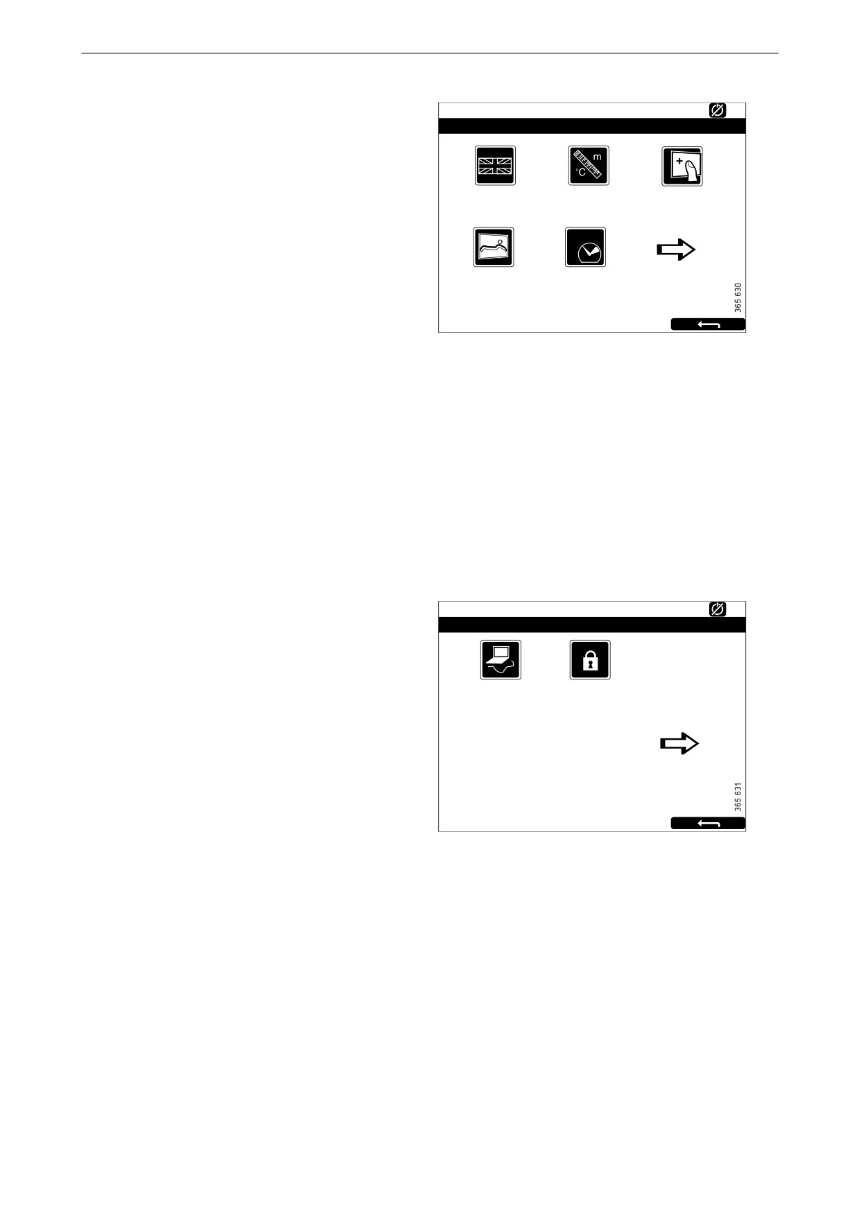
Language
Ready
Settings
123
Select language.
The languages which can be selected depend on
how the display is configured.
Language
Units
Calibrate Touch
[English]
[Metric]
Screen
Units
Select unit of measurement: Metric or U.S.
Wallpaper
Engine Overspeed
Calibrate Touch Screen
Test
[Inactive]
Calibrate the main display if necessary.
Wallpaper
Here you choose between different backgrounds
for instruments, menus and dialogue boxes.
Engine Overspeed Test
Select Active to activate the engine overspeed
test. When the overspeed test is activated, the
overspeed setting is temporarily reduced to a
nominal engine speed. Start the engine to carry
out the test.
The engine overspeed test is deactivated auto-
matically after a timeout or when actual engine
overspeed is detected in the test.
Connect a PC
Ready
Settings
123
This function is used when configuring the main
display and updating software. Contact an au-
thorised Scania workshop if any of this needs to
Connect a PC
Administration
be carried out.
[Locked]
Administration
In the administration section the main display is
configured, which can only be done by an au-
thorised Scania workshop. It is therefore pass-
word-protected.
16
Main display
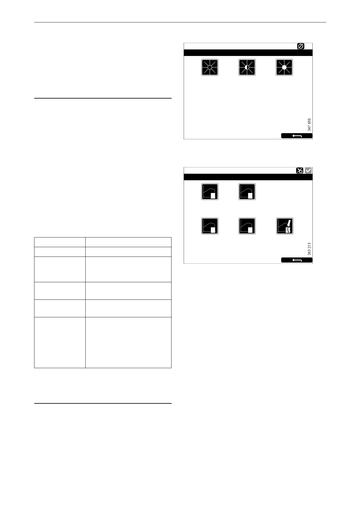
Screen Backlight
Ready
Backlight
The Screen Backlight button is in the Menu.
Note:
10 %
50 %
100 %
The button is only available if the display has
software version 2.11 or earlier.
When you press Screen Backlight, the Backlight
window opens. This increases and reduces the
brightness of the main display.
Torque Limit
Running
Torque Limit Selection
The Torque Limit button is in the Menu. When
you press it the Torque Limit Selection window
opens.
0
1
Cu r ve 0
Cu r ve 1
Torque limitation is different types of power
curves which the engine should follow. The
power curves are configured in SDP3.
2
3
Cu r ve 2
Cu r ve 3
Input Controlled
Adjustment
Description
[Cu r ve 0]
Curve 0
Maximum engine torque.
Curve 1
Maximum engine torque, an-
other lower engine torque re-
quested.
Curve 2
Customer defined engine
torque.
Curve 3
Customer defined engine
torque.
Input Controlled
Activation of curve 1-3 via in-
puts on the main display, if this
has been configured.
The button is only available if
the display has software ver-
sion 2.12.
Note:
Customer defined engine torques are always
lower than the maximum engine torque.
17
Main display
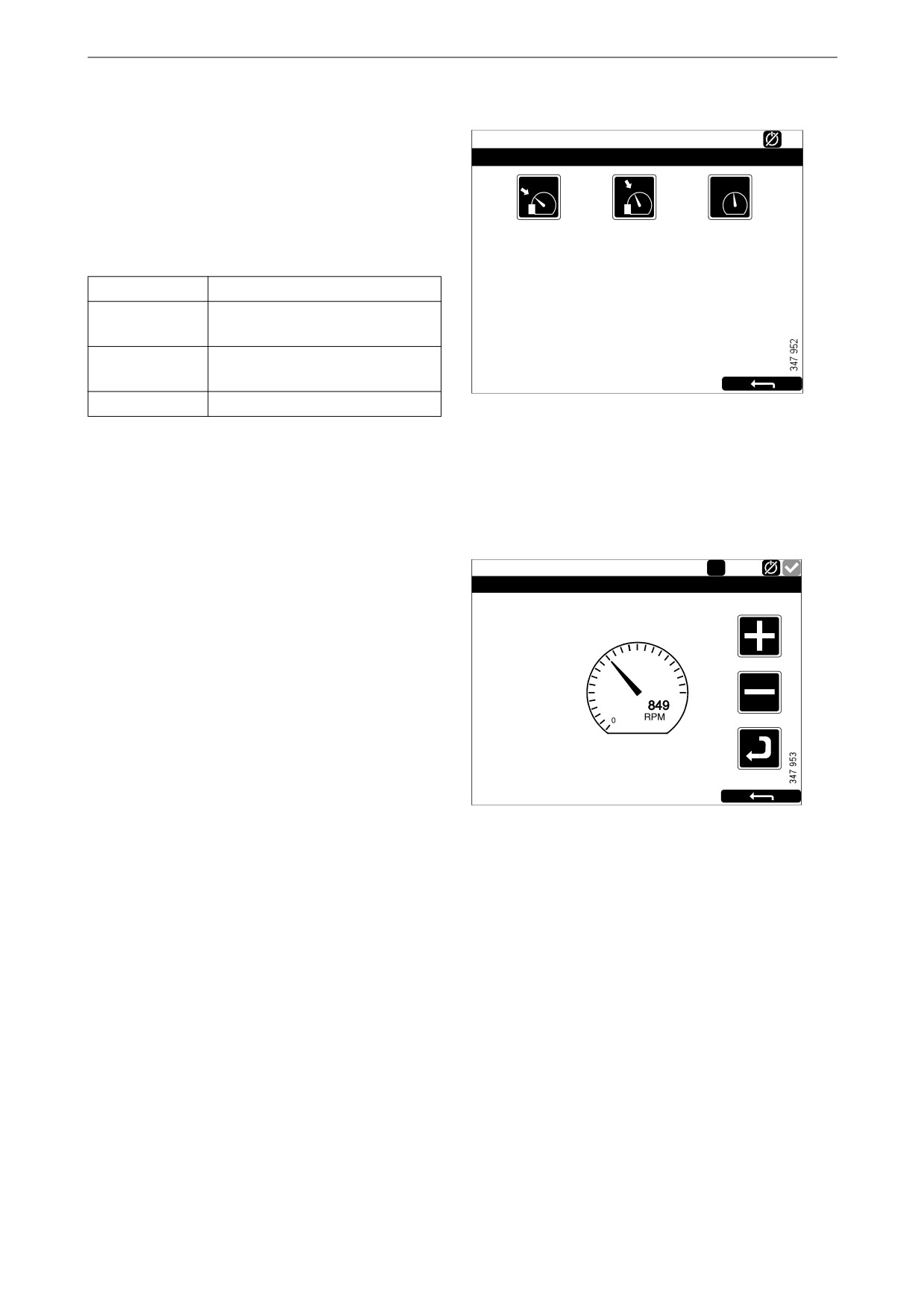
Fixed Speed
Running
The Fixed Speed button is in the Menu. When
Mode
you press it the Mode window opens.
Here you activate and deactivate the engine
1
2
speed setting. You can choose from the follow-
Fixed Speed Mode 1 Fixed Speed Mode 2 Fixed Speed Off
ing options:
Adjustment
Description
Fixed Speed
Activate engine speed setting 1.
Mode 1
Fixed Speed
Activate engine speed setting 2.
Mode 2
Fixed Speed Off
Deactivate engine speed setting.
In order to activate engine speed setting 1 or 2,
the engine must be running, the display must be
active and the throttle must be at 0%.
Adjust Fixed Speed
Running
1
The Adjust Fixed Speed button is in the Menu.
Fixed Speed Adjustment - Mode 1
When you press it the Fixed Speed Adjustment
window opens. Here you adjust engine speed
setting 1 and 2.
Engine Speed
1000
1500
You can only adjust an engine speed setting if
you have first activated it. This can be done in 2
500
2000
different ways:
• Via Menu > Fixed Speed in the main display,
see the previous section.
• Via the engine speed setting control in the
control panel, see the Control panelsection.
18
Main display
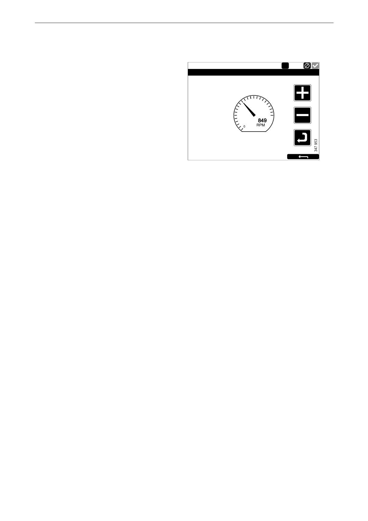
The following 2 engine speed settings are in Ad-
just Fixed Speed:
Running
1
• Fixed Speed Mode 1 is an engine speed which
Fixed Speed Adjustment - Mode 1
can be set between high and low idling. High
and low idling vary depending on the type of
engine.
Engine Speed
• Fixed Speed Mode 2 is an engine speed which
1000
1500
can be set between 450 and 2,000 rpm.
500
2000
Proceed as follows to adjust engine speed setting
1 or 2:
1. Select the engine speed setting to be adjust-
ed.
2. Press the activate button, i.e. the arrow but-
ton underneath the minus button for 3 to 6 s
to access the adjustment mode.
3. Step to the desired engine speed using the +
and - buttons.
4. Save the desired engine speed by keeping the
activate button pressed for 3 to 6 s. No con-
firmation is shown but the setting is saved.
5. Exit the menu by pressing the return arrow.
When either of the engine speed settings is acti-
vated, the engine speed goes up or down to the
last saved engine speed setting.
You can set torque limitation for both engine
speed settings via SDP3. The engine speed set-
tings are isochronous.
19

Main display
Log & Counters
The Log & Counters button is in the Menu.
Ready
Log & Counters
Here, a log of engine operating hours and all
warnings and alerts is shown. When you have
pressed Log & Counters, the following buttons
Counters
Event Log
Engine Se r vice
are shown:
Inte r val
Counters
This submenu contains counters for
Scania Fault
• the engine's total operating hours and fuel
Codes
consumption (Total).
• operating hours and fuel consumption since
start (Since Start).
• operating hours and fuel consumption since
reset (Since Reset).
The values for Since Start are reset automatically
each time the engine is started.
The values for Since Reset are reset by pressing
Reset at the bottom left of the Counters window.
Event Log
All events (warnings and alarms) are saved in the
main display and can be shown in this menu.
Select an event to see information on when it
first occurred, when it was acknowledged (if it is
possible to acknowledge the event) and when it
disappeared.
Engine Service Interval
Not used.
Scania Fault Codes
This shows Scania fault codes in DTC format.
These can make things easier when contacting a
Scania workshop.
Note:
The button is only available if the display has
software version 2.12.
20

Main display
Help
Ready
Help
The Help button is in the Menu. In Help there are
options for troubleshooting and for the main dis-
play software version and IP address.
Troubleshooting Version Information
Troubleshooting
Ready
Troubleshooting DCU
12
There are options here to troubleshoot the main
display.
Supply
Switch
4-20mA
First, press Troubleshooting DCU. Then select
using the buttons within the area in which the
troubleshooting should be carried out. Note that
there are 2 pages of options.
PT100
Communication
Version Information
Ready
Version Information - DCU 210
Information about the main display hardware
Engine #1
version, software version and operating system
Hardware Version:
4
Software Version:
2.12B10 - Build: 13107
is shown here. When connecting via CAN, the
Kernel Version:
120223
SDU Software Version:
1.43
software version of the engine control unit is
IP Address:
192.168.0.101
MAC Address:
00:14:2D:21:BC:8A
shown.
Cfg: DnVTypeApprovalConfig
The IP address of the display, which is needed if
the main display is to be connected to a PC, is
also shown here.
21

Auxiliary display
Auxiliary display
The auxiliary display largely works in the same
way as the main display. Therefore, only aspects
specific to the auxiliary display are described
here.
The auxiliary display reads the configuration
from the main display it is connected to. If the
configuration of the main display has been
changed, the auxiliary display adapts automati-
cally to the new configuration.
The auxiliary display can only monitor and con-
trol a main display.
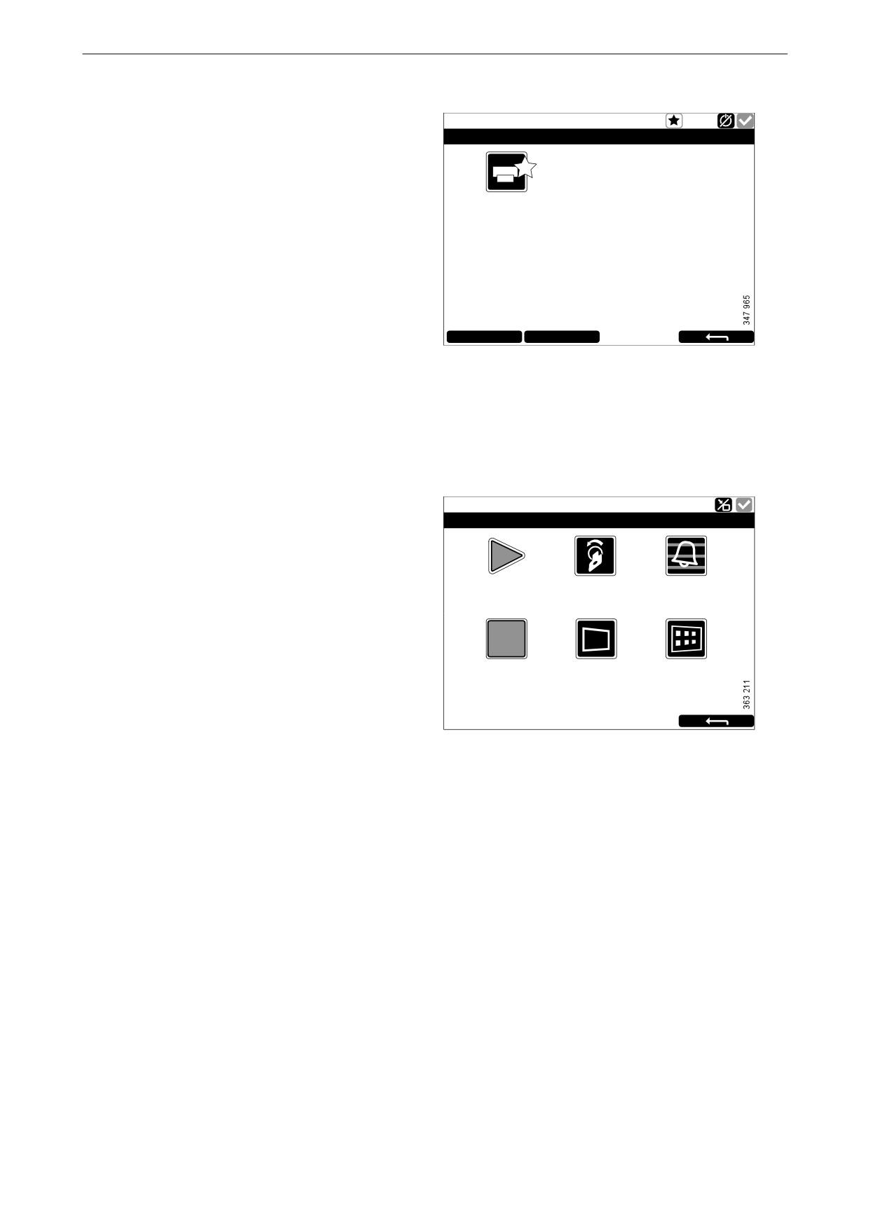
Symbols in the status bar
In addition to the symbols shown in the main dis-
play (see the Main display layoutsection), the ac-
tive display symbol can also be shown in the
auxiliary display status bar. See illustration.
Active display symbol in the auxiliary display
22

Auxiliary display
Menu
Engine # 1 - Ready
Menu
12
You get to the auxiliary display main menu in the
same way as with the main display:
Settings
Backlight
Torque Limit
[100%]
[Curve 0]
• Press in the middle of the display for 1 s. on
one of the instrument pages, or
• press the Menu button in the Shortcut Menu
window.
Fixed Speed
Adjust Fixed Speed
[Off]
When the main menu is opened the most recently
used function is preselected.
In the following section only the Settings and Ac-
Menu, page 1
tive Station buttons are described, as all the other
buttons work in the same way as with the main
display.
Engine # 1 - Ready
Menu
12
Active Station
Log & Counters
Camera
[None]
Settings
Help
The Settings button is the first button on page 1
of the Menu. In this section only the Sound but-
ton is described, as all the other buttons in Set-
tings have the same function as in the main
display.
Menu, page 2
Sound
The auxiliary display has a 3.5 mm output for
Engine # 1 - Ready
connection of external loudspeakers. The sound
Sound
from external loudspeakers is different to the
sound from the buzzer, and different sounds are
connected to different events.
Button Beep
Sound
[Enabled]
Configuration
• With the Sound Configuration button, select
[Buzzer]
either external loudspeaker or the inbuilt
buzzer.
Settings > Sound
23

Auxiliary display
Active Station
Auxiliary # 8 - Running
Active Station
The Active Station button is the first button on
page 2 of the Menu.
Here, you activate and deactivate the option for
Running
the auxiliary display to have active display sta-
[This Station]
Auxiliary #8
tus, i.e. Active Station.
There may be several auxiliary displays in the
system controlling the same engine, but only one
auxiliary display can be active at any time.
Request
Release
Activating Active Station status
How to request that the auxiliary display become
an active display:
• Select an engine and press Request.
A request is sent to the auxiliary display which
currently has active display status.
If the engine icon has a yellow star in the status
bar at the top of the window, as in the illustration,
this means that the engine is currently being con-
trolled by this auxiliary display.
Note:
If there is only one auxiliary display in the sys-
tem, it still may not be the active display.
When you have activated Active Station once,
the setting is saved, even when the auxiliary dis-
play is restarted.
24
Alarm list
Deactivating Active Station status
Auxiliary # 8 - Running
Active Station
You can also deactivate the auxiliary display Ac-
tive Station status. Other auxiliary displays with
lower priority can then control the engine. Pro-
ceed as follows:
Running
[This Station]
Auxiliary #8
• Select an engine and press Release.
Request
Release
Alarm list
Ready
Sho r tcut Me nu
The alarm list is displayed and functions in the
0
1
same way on the main display and the auxiliary
display. In the alarm list warnings and diagnosis
Sta r t Engine
Ignition off
Ala r m List
messages are also shown.
There are 2 different ways to get to the alarm list
in the main display and auxiliary display:
Stop Engine
Bla ck Panel Mode
Me nu
• Press in the upper right-hand corner on one of
[Ena bled]
the instrument pages.
• Press the Alarm List button in the Shortcut
Menu window.
25

Alarm list
Typefaces and background
colours
Ready
Alarm list
All Alarms
The following principles apply to how warnings
2: Throttle Position
and alarms are shown in the alarm list:
• An event which is not acknowledged is dis-
played using bold.
• An acknowledged event is displayed using
normal text.
• An alarm and an engine shutdown are dis-
played using a red background. During en-
gine shutdown, a stop signal is also displayed.
Ack Alarms
Panel Alarms
Engine Diag.
• A warning is displayed using a yellow back-
ground.
• A diagnosis message is displayed using a
white background.
• An event which is not acknowledged and has
turned inactive is displayed using a grey
background.
Example: The coolant temperature has ex-
ceeded the limit value and then returned to a
normal level before the operator has had time
to acknowledge the event.
This table lists examples of how different
events are shown in the alarm list.
Alarm list
Type of alarm
Display
New active alarm or engine shutdown.
Bold with red background.
Acknowledged active alarm or engine shutdown.
Red background.
Not acknowledged inactive alarm.
Red text with grey background.
New active warning.
Bold with yellow background.
Acknowledged active warning.
Yellow background.
Not acknowledged inactive warning.
Yellow text with grey background.
New active diagnostic message.
Bold with white background.
Acknowledged diagnostic message.
White background.
Not acknowledged inactive diagnostic message.
Black text with grey background.
26

Alarm list
Filtering alarms
Ready
Alarm list
All Alarms
In the alarm list, the alarms can be filtered in 3
2: Throttle Position
different groups:
• All alarms
• Display alarms
• Diagnostics
You activate the different filters by pressing the
respective section at the bottom of the display.
On line 2 in the alarm list, the filter which is ac-
tive is displayed.
Ack Alarms
Panel Alarms
Engine Diag.
Turning off the buzzer during
an alarm
The buzzer is switched off when the alarm list is
opened. If the buzzer begins to sound when the
alarm list is open, you can switch it off by press-
ing Ack Alarms.
Acknowledging 1 alarm
In the alarm list:
• Select the alarm to be acknowledged. If there
is more information to display the row will be
extended.
• Press Ack Alarms.
Acknowledging all alarms
In the alarm list:
• Keep the Ack Alarms button depressed for 1
second.
Note:
Active alarms will remain in the alarm list.
Alarms from safety device unit
If the alarm is generated via the safety device
unit, it must be acknowledged in both the safety
device unit and on the main display.
27
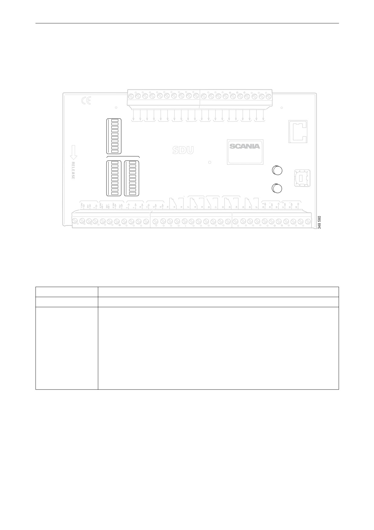
Safety device unit
Safety device unit
The safety device unit has its own monitors and sensors. An alarm which has been generated via the safety
device unit must also be acknowledged on the main display.
COM 3
STATUS
CONFIGURA TION
ETHERNET
PO WER
CRANK CUT OFF
SWITCH 1
SWITCH 2
SWITCH 3
SWITCH 4
SWITCH 5
SWITCH 6
SWITCH 7
SWITCH 8
SHUTDO WN
ACKNO WLEDGE
RUNNING
OVERRIDE
TACHO 1
TACHO 2
SHUTDO WN O VERRIDE
B UZZER
COM 1
COM 2
COM 3
shutdo wn unit
SHUTDO WN
FAULT
SWITCH 1
SWITCH 1
A CKNO WLEDGE
COM 4
SWITCH 2
SWITCH 2
USB
SWITCH 3
SWITCH 3
SWITCH 4
SWITCH 4
SWITCH 5
SWITCH 5
SWITCH 6
SWITCH 6
O VERSPEED
TEST
SWITCH 7
SWITCH 7
SWITCH 8
SWITCH 8
SHUTDO WN
SHUTDO WN COIL
CRANK
OVERSPEED
SHUTDO WN O VERIDE SHUTDO WN
CUT OFF
B UZZLER
FAULT
RUNNING
COM 2
COM 1
RS 485
SUPPL Y
SHUTDO WN COIL
TACHO 1
TACHO 2
DCU LINK
MODB US R TU
Safety device unit.
Buttons
Button
Description
Acknowledge
With the Acknowledge button all faults and engine shutdowns are acknowledged.
Overspeed Test
How to carry out an overspeed test: When the engine is switched off, keep the Over-
speed Test button depressed until the Overspeed LED starts flashing quickly. The safe-
ty device unit is now in test mode, and the limit value for engine overspeed is reduced
to 95% of the set overspeed limit value. Then start the engine.
The overspeed test can be deactivated in 3 different ways:
• The test is completed and is finished with an engine shutdown due to overspeed at
95% of the set overspeed limit value.
• Press the Overspeed Test button.
• Automatic deactivation after 5 minutes.
28

Safety device unit
LEDs
The LEDs indicate status, engine shutdown or faults. When an LED is flashing, there is a new event which
has not been acknowledged. When an LED is constantly on, there is an event which has been acknowledged
but which is still active.
Status LEDs
LED
Description
Power
Lights when the safety device unit is supplied with a voltage above 21 V. Flashes if
voltage is below 21 V. Alarm if voltage is below 21 V for more than 30 s. If voltage
drops to below 18 V the safety device unit switches off all channels.
Crank Cutoff
Lights when the engine speed is above the set limit value.
Running
Lights when the safety device unit gets a signal that the engine speed is above the set
limit value, which is normally 400 rpm.
Tacho 1/Tacho 2
Lights when the engine speed is above 5 rpm.
Shutdown Override
Lights when engine shutdown override control is activated.
Buzzer
Lights when the buzzer is activated.
COM 1
Flashes when the safety module communicates with the main display.
COM 2
Flashes when the safety module communicates via Modbus RTU interface.
COM 3
Flashes when the safety module communicates with the Ethernet interface.
LEDs for engine shutdown and faults
Shutdown
LED
Description
Switch 1
Lights at engine shutdown due to impermissible engine oil pressure.
Switch 2
Lights at engine shutdown due to high coolant temperature.
Switch 3
Lights at engine shutdown due to remote controlled emergency stop.
Switch 4
Lights at engine shutdown due to too high coolant pressure.
Switch 5-8
Lights at engine shutdown due to customer configured settings.
Shutdown
Lights at all engine shutdowns.
Overspeed
Lights at engine overspeed. Flashes rapidly at engine overspeed test.
Fault
LED
Description
Switch 1-8
Lights at open circuit for the respective sensor.
Shutdown Coil
Lights at open circuit for the Shutdown Coil output.
Shutdown Override
Lights at open circuit for the Shutdown Override input.
29
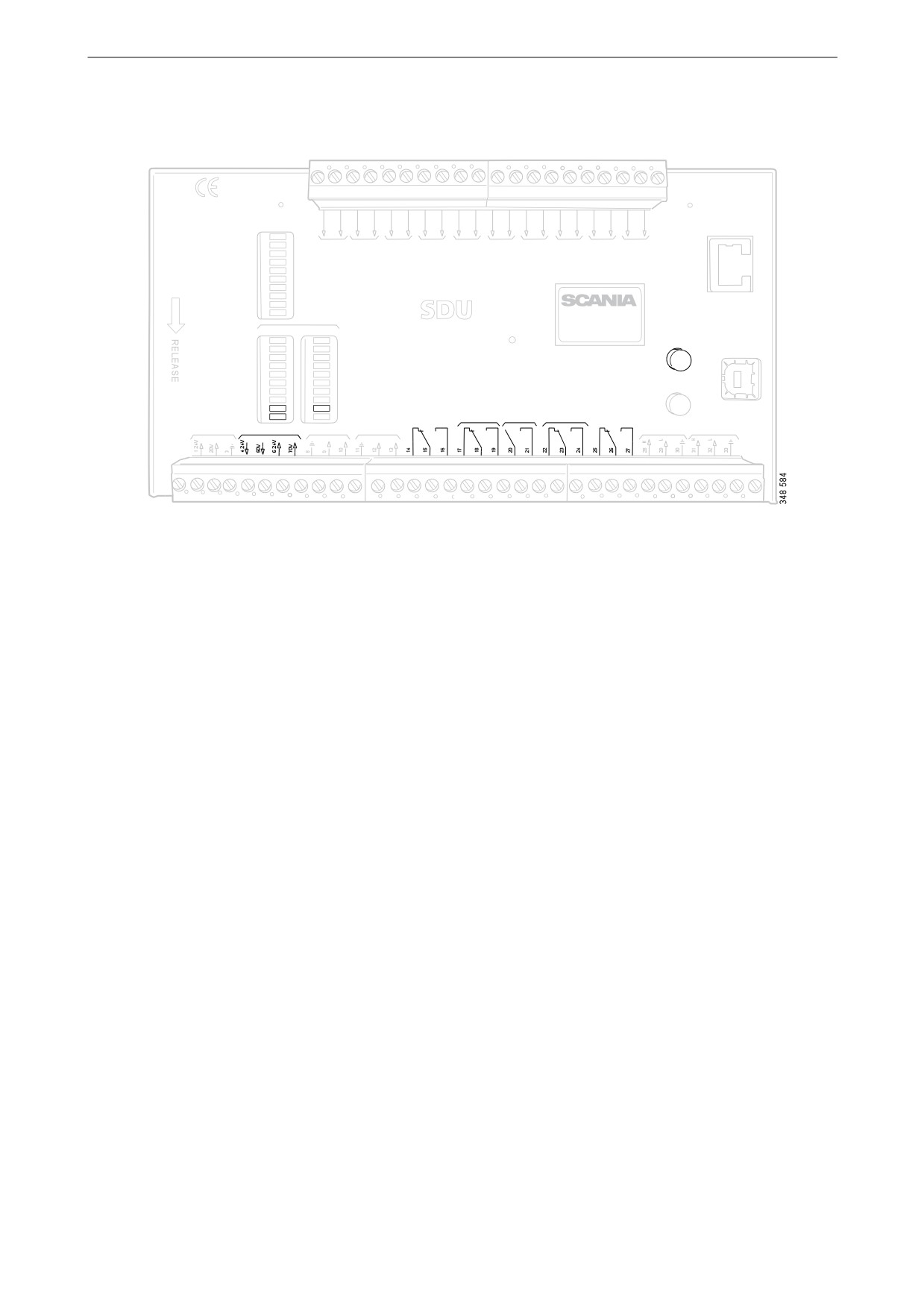
Safety device unit
Engine shutdown at engine overspeed
COM 3
STATUS
CONFIGUR ATION
ETHERNET
POWER
CRANK CU TOFF
SWITCH 1
SWITCH 2
SWITCH 3
SWITCH 4
SWITCH 5
SWITCH 6
SWITCH 7
SWITCH 8
SHUTD OWN
A CKN OWLEDGE
R UNNING
OVERRIDE
TACHO 1
TACHO 2
SHUTD OWN OVERRIDE
B UZZER
COM 1
COM 2
COM 3
shutd o wn unit
SHUTD OWN
FAULT
SWITCH 1
SWITCH 1
A CKN OWLEDGE
COM 4
SWITCH 2
SWITCH 2
USB
SWITCH 3
SWITCH 3
SWITCH 4
SWITCH 4
SWITCH 5
SWITCH 5
SWITCH 6
SWITCH 6
OVERSPEED
TEST
SWITCH 7
SWITCH 7
SWITCH 8
SWITCH 8
SHUTD OWN
SHUTD OWN COIL
CRANK
OVERSPEED
SHUTD OWN OVERIDE SHUTD OWN
CU TOFF
B UZZLER
FAULT
R UNNING
COM 2
COM 1
RS 485
SUPP LY
SHUTD OWN COIL
TACHO 1
TACHO 2
DCU LINK
MOD B US R TU
Safety device unit.
If a signal is sent to one of the 2 engine speed inputs that the engine speed exceeds the limit value, the safety
device unit shuts off the engine.
Override of engine shutdown
It is not possible to override engine shutdown at engine overspeed. The engine is always shut off in case of
engine overspeed.
Indication
The red Overspeed LED lights. The red Shutdown LED lights.
Acknowledgement
When engine shutdown has occurred: Acknowledge the engine shutdown with the Acknowledge button on
the safety device unit.
30

Safety device unit
Engine shutdown due to sig-
Shutdown Coil
nal from sensor
The Shutdown Coil output is activated at all en-
gine shutdowns. The output is deactivated
If any of the sensors indicates engine shutdown
8 seconds after the engine has stopped.
the safety device unit activates engine shutdown.
Detecting an open circuit
Override of engine shutdown
If there is an open circuit in the electrical cables
All sensor channels can be configured to disre-
connected to junction block 4 and 5, the red
gard the engine shutdown override signal.
Shutdown Coil LED lights. The impedance
should be in the region of 300-700 ohms.
Indication
The red Switch LED for the corresponding sen-
Power supply
sor lights. The red Shutdown LED lights.
Shutdown Coil is supplied with power separately
via junction block 6 and 7.
Acknowledgement
When engine shutdown has occurred: Acknowl-
edge the engine shutdown with the Acknowledge
button on the safety device unit.
Relays
Relay
Description
Shutdown
Is activated at all engine shutdowns. Active until the engine has been stopped and the
operator has acknowledged the event.
Crank Cutoff
Is activated at a set engine speed, which is normally 400 rpm. Is deactivated when the
safety device unit has obtained a signal that the engine has stopped.
Buzzer
Is activated for all new engine shutdowns and faults. Is deactivated when the operator
has acknowledged the event.
Fault
Fault indicator, i.e. is activated for all new faults. Is deactivated when the fault has been
acknowledged and has disappeared.
Running
Is activated at a set engine speed, which is normally 400 rpm. Is deactivated when the
safety device unit has obtained a signal that the engine has stopped.
31