Scania 2.0 Instrumentation en-GB 2 495 120. Operator's manual - part 1
Operator's manual
Scania 2.0
Instrumentation
en-GB 2 495 120
Issue 2.0
Introduction
3
Responsibility
3
Display languages
3
Software versions
3
System overview
4
Main display
5
Auxiliary display
5
Network switch
5
Safety device unit
5
Gateway
5
Control panel
5
Main display
6
Password
6
Navigation
6
Main display layout
10
Starting the engine
11
Stopping the engine
11
Switch off the voltage
11
Switching off the display
12
Alarm
12
Menu
13
Auxiliary display
22
Symbols in the status bar
22
Menu
23
Alarm list
25
Typefaces and background colours
26
Filtering alarms
27
Turning off the buzzer during an alarm
27
Acknowledging 1 alarm
27
Acknowledging all alarms
27
Safety device unit
28
Buttons
28
LEDs
29
Engine shutdown at engine overspeed
30
Engine shutdown due to signal from sensor .
31
Relays
31
Shutdown Coil
31
2
Introduction
Introduction
Software versions
The main display interface differs depending on
This Operator's manual describes the operation
which software version is installed.
of Scania instrumentation.
You can check the software version by going to
The information in this manual was correct at the
Menu > Help > Version Information.
time of going to press. Scania reserves the right
to make alterations without prior notice.
Ready
Version Information - DCU 210
Note:
Engine #1
Always use Scania spare parts for maintenance
Hardware Version:
4
Software Version:
2.12B10 - Build: 13107
and repair.
Kernel Version:
120223
SDU Software Version:
1.43
IP Address:
192.168.0.101
MAC Address:
00:14:2D:21:BC:8A
Cfg: DnVTypeApprovalConfig
The user of this Operator's manual is expected to
have a basic understanding of marine electrical
systems and to be able to carry out work on elec-
trical systems.
REQUIREMENT!
Work on the low voltage circuit should only be
carried out by qualified and experienced person-
nel.
Work on the high voltage circuit may only be
carried out by an authorised electrician.
Responsibility
It is the responsibility of the installer to ensure
that the installation of the electrical system is
carried out in a professional manner. It is also the
responsibility of the installer to ensure that the
system is working satisfactorily and that all com-
ponent parts meet legal requirements and regula-
tions.
Display languages
In this Operator's manual the display interfaces
are shown in English. It is however possible to
set other languages.
3
System overview
System overview
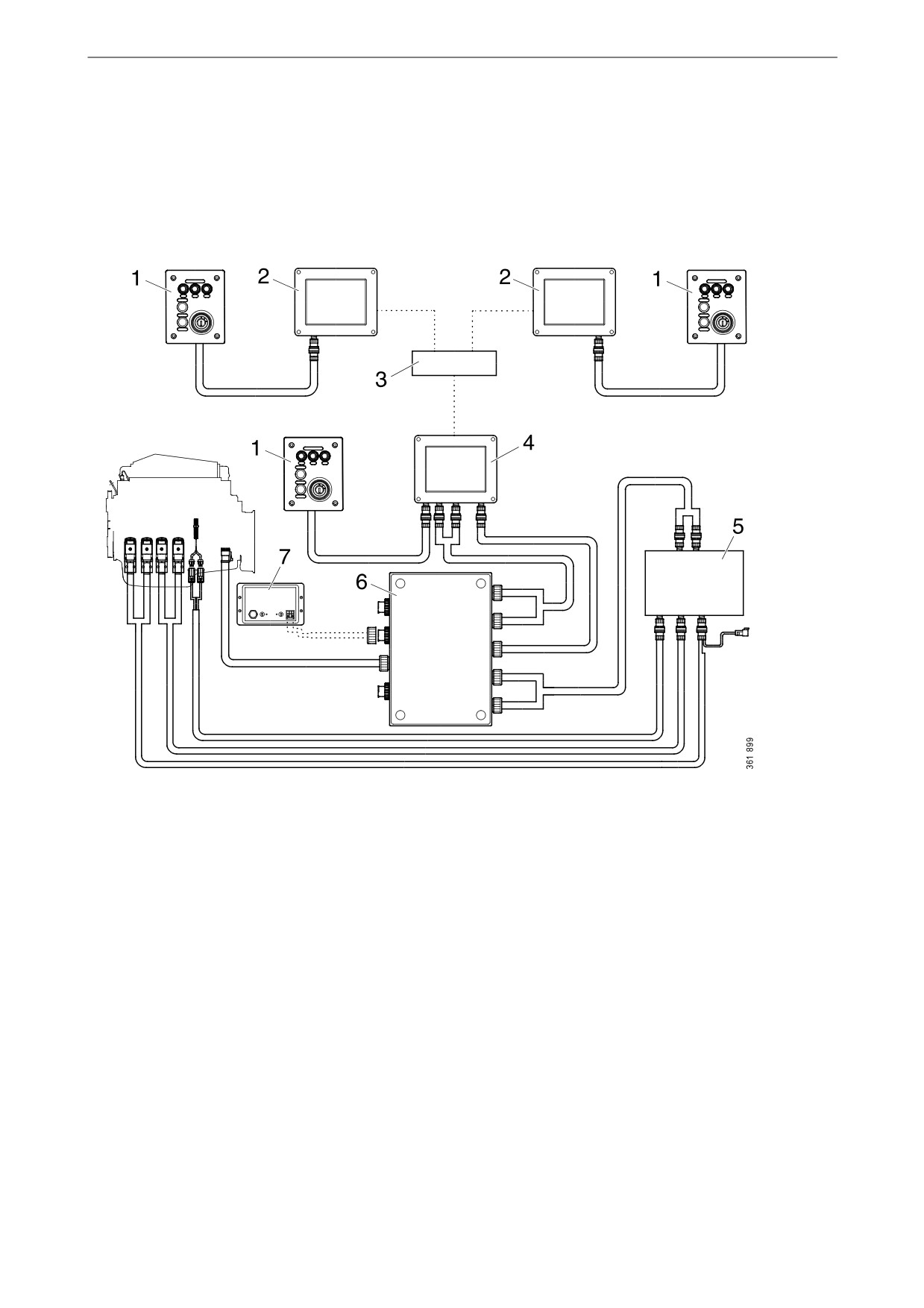
The illustration shows how a control system pre-
pared for classification may be designed.
1. Control panel.
2. Auxiliary display.
3. Network switch.
4. Main display.
5. Safety device unit.
6. Junction box.
7. Gateway.
4
System overview
Main display
Control panel
The main display is the main component in the
The engine can be started and stopped through
control system. Values from the engine sensors
the control panel. It is also possible to activate
are shown on the display. Commands and other
engine speed setting 1 and 2 through it.
user functions are also carried out on the main
display.
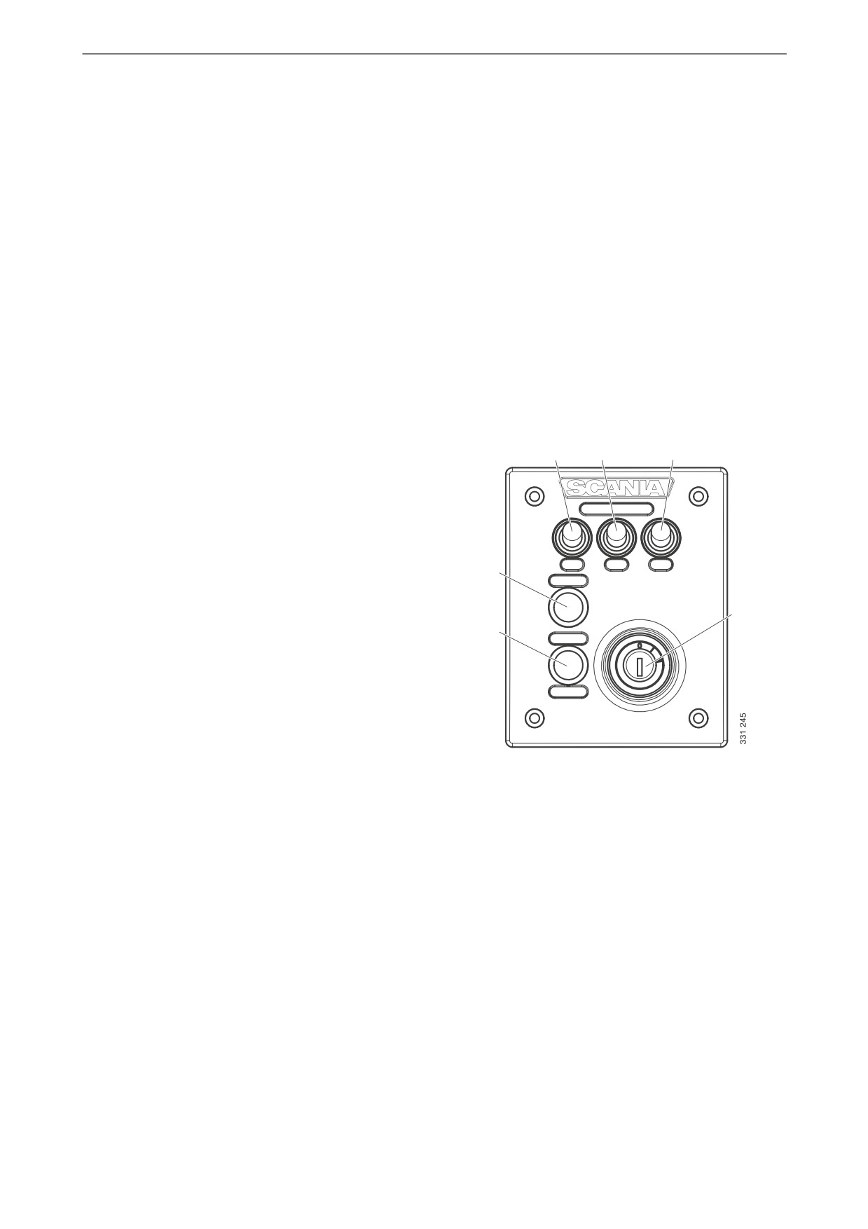
Starter lock
The control panel starter lock (4) is used to start
Contact an authorised Scania workshop if the
and stop the engine. The starter lock has the fol-
main display needs to be configured.
lowing positions:
Auxiliary display
• Position 0: The engine electrical system is
switched off and the engine is stopped.
The auxiliary display, which is optional, shows
• Position 1: The engine electrical system is ac-
the same things as the main display, with the
tivated.
same user interface.
• Position 2: The starter motor is activated.
The auxiliary display does not need to be config-
ured as it reads the configuration from the main
display. Therefore, it is easy to supplement the
control system with an auxiliary display after-
1
2
3
wards.
Network switch
A network switch is only required if more than
1 auxiliary display is connected to the control
system. The displays can then be connected to-
6
gether via a network cable.
4
Scania recommends using a network switch, in
order to make it simpler to expand the control
5
system and connect a computer.
Safety device unit
The safety device unit is a requirement for clas-
sified control systems. The safety device unit has
the same monitoring and shut-off functions as
the main display.
Control panel
1. Control for activating engine speed
Gateway
setting 1.
2. Control for activating engine speed
The gateway reads messages about position and
setting 2.
speed via NMEA 2000, so that the control sys-
tem can calculate fuel consumption per nautical
3. Control for deactivating engine speed
mile.
setting 1 or 2.
4. Starter lock.
5. Not used.
6. Not used.
5

Main display
Main display
The function of the main display depends on how
it is configured. Configuration of the main dis-
play is not described in this Operator's manual.
Password
If the control system is not equipped with a con-
trol panel, a 4-digit password is used instead of a
starter key. The password is provided by the in-
staller.
Navigation
The main display is a touch screen where you
carry out every command by pressing directly on
the display. The main display has 5 different
view modes:
• Instrument pages
• Select Page
• Shortcut Menu
• Alarm List
• Menu
Different touch areas on the display have differ-
ent functions. For example, if you touch the left-
hand side of the display on an instrument page,
you get to the previous instrument page.
How to navigate:
To get to
Pressure
Select Page
in the middle of the dis-
play
previous instrument
on the left of the display
page
next instrument page
on the right of the dis-
play
Shortcut Menu
in the top left-hand cor-
ner
Alarm List
in the top right-hand
corner
Menu
a long press (1 s) in the
middle of the display
6

Main display
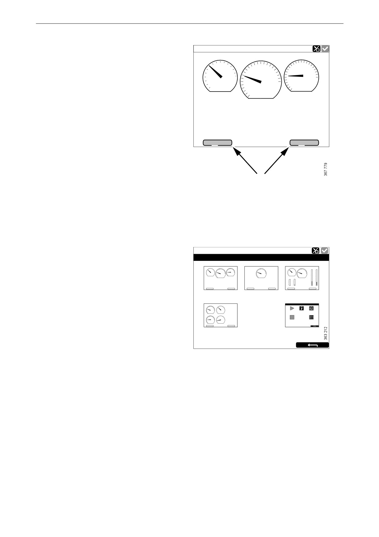
Instrument pages
There are 4 preset instrument pages. If another
instrument page has been configured, there can
be a total of 5 instrument pages.
Running
Running
Coolant Tem p.
Engine Speed
Engine Oil Pres s.
Engine Speed
6.0
100
1500
1500
80
1000
4.0
8.0
1000
2000
2000
60
120
10.0
2.0
80
500
2500
2.5
500
2500
40
°C
651
0.0
bar
651
0
RPM
0
Batte r y Voltage
Engine Hours
28,0
V
13
h
Engine Hours
Batte r y Voltage
13
h
28,0
V
BL -
BL +
BL -
BL +
Running
Running
Coolant Tem p.
Engine Speed
Engine Oil
Boost
Engine Speed
Coolant Tem p.
Batte r y Voltage
Pres
s.
Pressure
100
10.0
5.00
1500
28,0
V
80
1500
1000
80
100
1000
2000
2000
60
120
Fuel Rate
8.0
4.00
500
2500
60
120
500
2500
651
2,6
l/h
80
40
°C
651
0
RPM
40
6.0
3.00
°C
0
RPM
Throttle Position
Throttle
Engine Oil Pres s.
Boost Pressure
Position
% Load
0
%
4.0
2.00
100
100
6.0
3,00
Engine Hours
4.0
8.0
2,00
4,00
% Load
13
h
50
50
1.00
11
%
2.0
10.0
1,00
5,00
Fuel Rate
2.5
1,06
0
0
0.0
0.00
0.0
0,00
bar
Engine Oil Tempe rature
2.6
l/h
0 %
11 %
2.5
bar
1.06
bar
80
°C
BL -
BL +
BL -
BL +
The 4 preset instrument pages.
You scroll between the instrument pages by
pressing on the right- or left-hand side of the dis-
play.
7
Main display
Adjusting the brightness of the display
Ready
Coolant Tem p.
Engine Speed
Engine Oil Pres s.
If the display has software version 2.12, you can
6.0
80
100
1500
1000
4.0
8.0
increase and reduce the brightness of the display
2000
60
120
10.0
by pressing BL- and BL+ on the instrument pag-
2.0
80
500
2500
2.5
es.
40
0.0
°C
651
bar
0
RPM
If the display has software version 2.11 or earli-
er, the brightness of the display is instead adjust-
Batte r y Voltage
ed using the Screen Backlight button in Menu.
28,0
V
See Screen Backlight.
Engine Hours
13
h
BL -
BL +
Increase and reduce the brightness of the display.
Select Page
Ready
Select Page
In Select Page thumbnails of the instrument pag-
CoolantTemp.
Engine Speed
Engine Oil Ps
Engine Speed
CoolantTemp.
Engine Speed
Press.
Engine Oil
BoostPressure
80
100
10001500
4.0
6.0
8.0
100015002000
80
100
10001500
10.0
5.00
es and the Shortcuts menu are shown.
6
0
120
2000
2.0
10.0
60
120
2000
8.0
4.00
40
80°C
500
651
2500
0.0
bar
2.5
500
651
2500
40
°C
500
651
2500
0
RPM
0
0
RPM
6.0
3.00
ThrottlePosition
% Load
4.0
2.00
Batt
ry Voltage
Engine Hours
100
100
Engine Hours
28,0
V
13
h
50
50
13
h
1.00
You get to Select Page by pressing in the middle
13
Engine Hours
h
Batt
28,0
ry Voltage
V
00 %
011 %
2.6
Fuel Rate
l/h
2.5
0.0
bar
1.06
0.00
bar
BL -
BL +
BL -
BL +
BL -
BL +
of the display.
Page 1
Page 2
Page 3
Engine Speed
CoolantTem
p.
Batt
ry Voltage
Sho r tcut Me n u
Then select one of the instrument pages or the
10001500
2000
80
100
28,0
V
0
1
500
2500
6
0
120
Fuel Rate
0
RPM
651
40
°C80
2,6
l/h
Sta r t Engine
Ignition off
Ala r m List
Shortcuts menu among the thumbnails.
Engine Oil P
s.
Boost Pressure
ThrottlPosition
0
%
4.0
6.0
8.0
2,003,00
4,00
% Load
2.0
10.0
1,00
5,00
11
%
Stop Engine
Me n u
0.0
2.5
0,00bar
1,06
Engine
Temp
rature
80
°C
BL -
BL +
Page 4
Sho r tcuts
Select Page, example with 4 instrument pages.
8
Main display
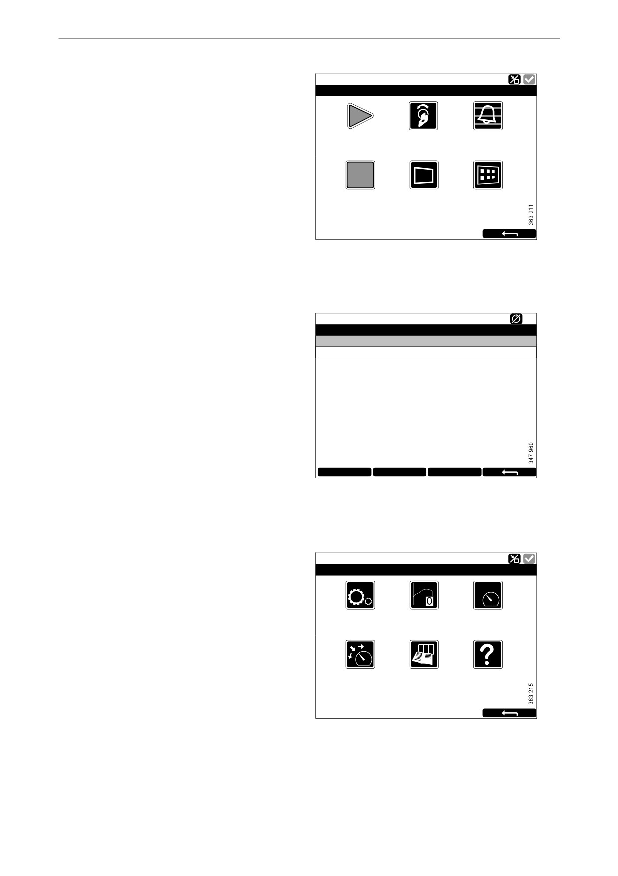
Shortcut Menu
Ready
Sho r tcut Me nu
In the Shortcut Menu window, there are the but-
tons Start Engine, Stop Engine, Alarm List and
0
1
Menu. If the display has software version 2.12,
Sta r t Engine
Ignition off
Ala r m List
there are also the Ignition Off and Black Panel
Mode buttons.
There are 2 different ways to get to the Shortcut
Menu:
Stop Engine
Bla ck Panel Mode
Me nu
[Ena bled]
• Press the upper left-hand corner of the dis-
play.
• Press the Shortcuts button in the Select Page
window.
Then select one of the functions or go back to Se-
lect Page by pressing the return arrow.
Ready
Alarm List
Alarm list
All Alarms
There are 2 different ways to get to the Alarm
2: Throttle Position
List:
• Press the upper right-hand corner of the dis-
play.
• Press the Alarm List button in the Shortcut
Menu window.
The Alarm List is described in the Alarm listsec-
tion.
Ack Alarms
Panel Alarms
Engine Diag.
Menu
Ready
Menu
There are 2 different ways to get to the Menu:
• Press in the middle of the display for 1 s. on
one of the instrument pages.
Settings
Torque Limit
Fixed Speed
[Curve 0]
[Off]
• Press the Menu button in the Shortcut Menu
window.
4
23
5
When the main menu is opened the most recently
Adjust Fixed Speed Log & Counters
Help
used function is preselected. For further informa-
tion on the functions, see the Menusection.
Menu, software version 2.12.
9

Main display
Main display layout
Status bar
On the upper part of the display there is a status
Ready
bar. Engine status is displayed on the left-hand
Coolant Tem p.
Engine Speed
Engine Oil Pres s.
side of the status bar and the display status on the
6.0
80
100
1500
1000
4.0
8.0
right-hand side.
2000
60
120
10.0
2.0
80
500
2500
2.5
40
°C
651
0.0
bar
0
RPM
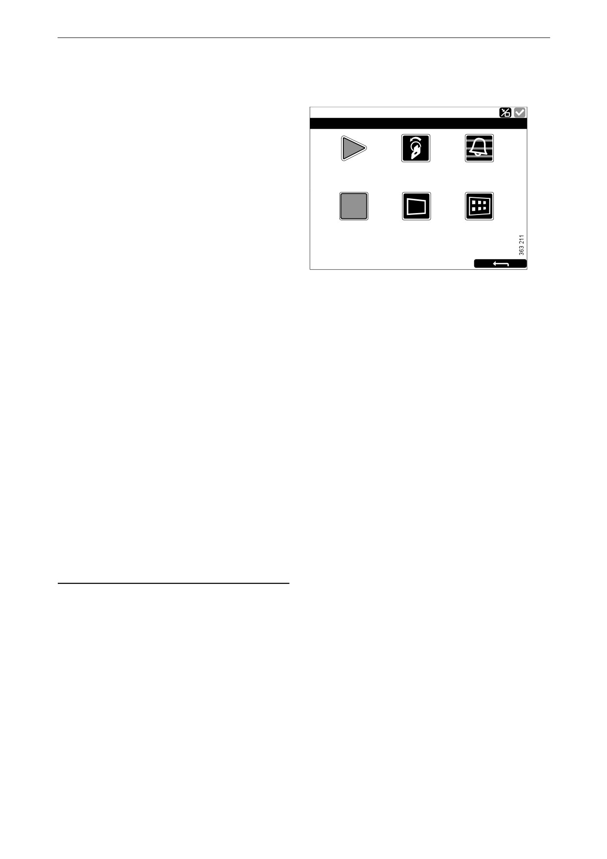
Display status symbols in the status
Batte r y Voltage
bar
28,0
V
The following display status symbols may be
Engine Hours
shown on the right-hand side of the status bar:
13
h
BL -
BL +
Status bar on an instrument page.
Symbol
Meaning
Explanation
Remote mode
The engine can be started and stopped from both the main display
and an auxiliary display.
Local mode
The engine can only be started and stopped from the main display.
Override of engine
If this function is activated, an alarm is only given for events which
shutdown
normally lead to engine shutdown. The exception is engine over-
STOP
speed, which is always activated.
Everything OK
There are no alarms in the alarm list.
Note:
Several symbols can be shown simultaneously.
10

Main display
Starting the engine
Keep the Start Engine button in the Shortcut
Ready
Menuwindow pressed until the engine has start-
Sho r tcut Me nu
ed. When the engine has started the status in the
top left of the status bar changes from Ready to
0
1
Running.
Sta r t Engine
Ignition off
Ala r m List
Stopping the engine
Stop Engine
Bla ck Panel Mode
Me nu
[Ena bled]
Keep the Stop Engine button in the Shortcut
Menu window pressed until the engine has
stopped. When the engine has stopped the status
in the top left of the status bar changes from Run-
ning to Ready.
Switch off the voltage
Press the Ignition Off button in the Shortcut
Menu window, or wait until the preset timer has
counted down to zero.
Note:
If there are multiple displays in the system, any
of these can keep the system running.
Note:
The button is only available if the display has
software version 2.12.
11
Main display
Switching off the display
The Black Panel Mode function in the Shortcut
Ready
Menu window is used to switch off the display to
Sho r tcut Me nu
improve visibility in the dark.
0
1
Press the button to switch off the display com-
pletely. If you touch the display when the func-
Sta r t Engine
Ignition off
Ala r m List
tion is activated, the display comes on at
minimum brightness, and is switched off auto-
matically again after a preset time. The standard
setting is 5 seconds.
Stop Engine
Bla ck Panel Mode
Me nu
In the case of a serious faults, the display comes
[Ena bled]
on even if Black Panel Mode is activated. How-
ever, with a less serious fault, only the buzzer
sounds.
The function is deactivated by pressing the but-
ton again.
Alarm
Each time a new alarm is added to the alarm list,
the following happens:
• The buzzer sounds.
• The status bar flashes either yellow or red.
The colour in the status bar has different mean-
ings:
• Yellow means warning.
• Red means alarm or engine shutdown.
Note:
A red alarm always takes precedence over a yel-
low warning if both are generated simultaneous-
ly.
For further information on alarms, see the sec-
tion Alarm list.
12

Main display
Menu
Ready
Menu
The main menu consists of 1 page if the display
has software version 2.12, and 2 pages if the dis-
play has software version 2.11 or earlier. The
Settings
Torque Limit
Fixed Speed
buttons in Menu are described in the following
[Curve 0]
[Off]
pages.
4
23
5
Note:
Adjust Fixed Speed
Log & Counters
Help
The Screen Backlight button is only available if
the display has software version 2.11 or earlier.
Menu, software version 2.12.
Ready
Ready
Menu
12
Menu
12
Settings
Screen Backlight
Torque Limit
Log & Counters
Help
[100%]
[Curve 0]
Fixed Speed Adjust Fixed Speed
[Off]
Menu, page 1, software version 2.11 or earlier.
Menu, page 2, software version 2.11 or earlier.
13

Main display
Settings
Ready
Ready
Settings
123
Settings
123
STOP
Mode
Start Disabled
Shutdown Override
Language
Units
Calibrate Touch
[Remote]
[Inactive]
[Inactive]
[English]
[Metric]
Screen
Prelube Override
Button Beep
Wallpaper
Engine Overspeed
[N/A]
[Disabled]
Test
[Inactive]
Settings, page 1.
Settings, page 2.
The Settings button is the first button in the
Ready
Menu. This is where you carry out all the display
Settings
123
settings. Settings consists of 3 pages.
The settings in Settings are described in the fol-
lowing pages.
Connect a PC
Administration
[Locked]
Note:
The position of the buttons on the screens differs
depending on whether the display has software
version 2.11 or earlier, or 2.12. Shutdown Over-
ride is only available if the display has software
version 2.12.
Settings, page 3.
14
Main display
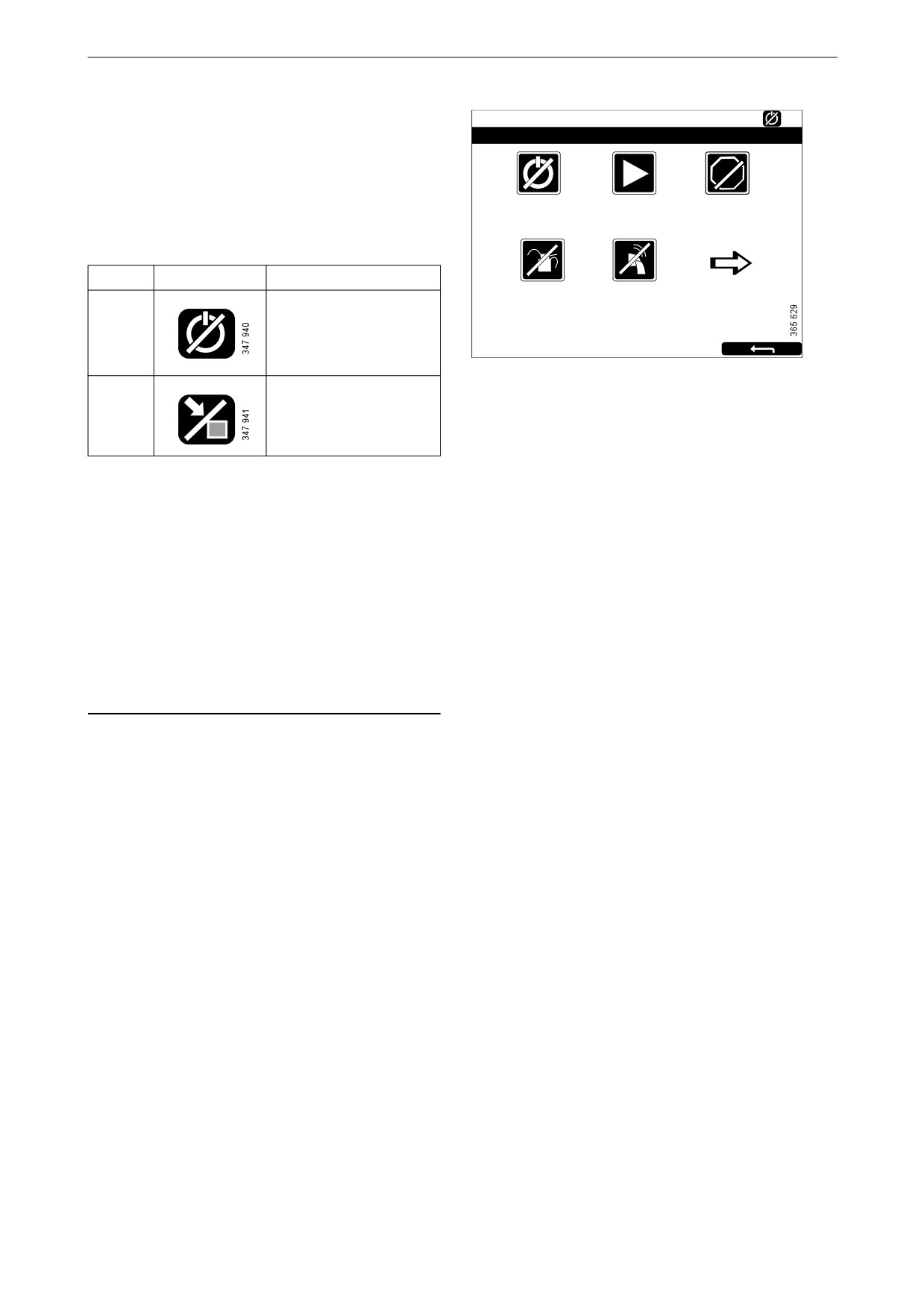
Mode
Ready
Settings
123
Here you select the operating mode of the dis-
play. There are 2 modes to choose from:
STOP
Mode
Start Disabled
Shutdown Override
[Remote]
[Inactive]
[Inactive]
Mode
Symbol
Explanation
Prelube Override
Button Beep
Remote
The engine can be start-
[N/A]
[Disabled]
ed and stopped from
both the main display
and an auxiliary display.
Local
The engine can only be
started and stopped
from the main display.
Start Disabled
Select Active to deactivate engine start.
Shutdown Override
Select Active to activate engine shutdown over-
ride control.
Note:
The button is only available if the display has
software version 2.12.
Prelube Override
Not used.
Button Beep
Select Enabled if you want a sound to be made
every time you press the display. Select Disabled
if no sound should be made when you press the
display.
15