Scania 4000 Instrumentation en-GB 2 268 463. Operator’s manual - part 2
Display navigation
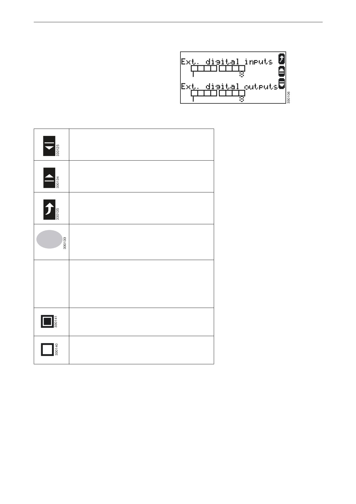
Digital inputs and outputs 1-8
This view is available in all operating modes.
This view is displayed when the display button
for next view is pressed if an external expansion
board has been connected to the instrument pan-
el.
The status of digital inputs and outputs 1-8 is dis-
played.
Digital inputs and outputs 1-8
Navigate to the next view.
Navigate to the previous view.
Return to the Home view.
Switch to operating mode stop.
STOP
Displays the status of digital inputs and outputs 1-8.
The configuration of the input determines how the
instrument panel reacts. If the input is configured as
normally open it will react when it is energised. If the
input is configured as normally closed it will react
when it is de-energised.
Displays that a digital input is energised or that a dig-
ital output is active.
Displays that a digital input is de-energised or that a
digital output is inactive.
16
Display navigation
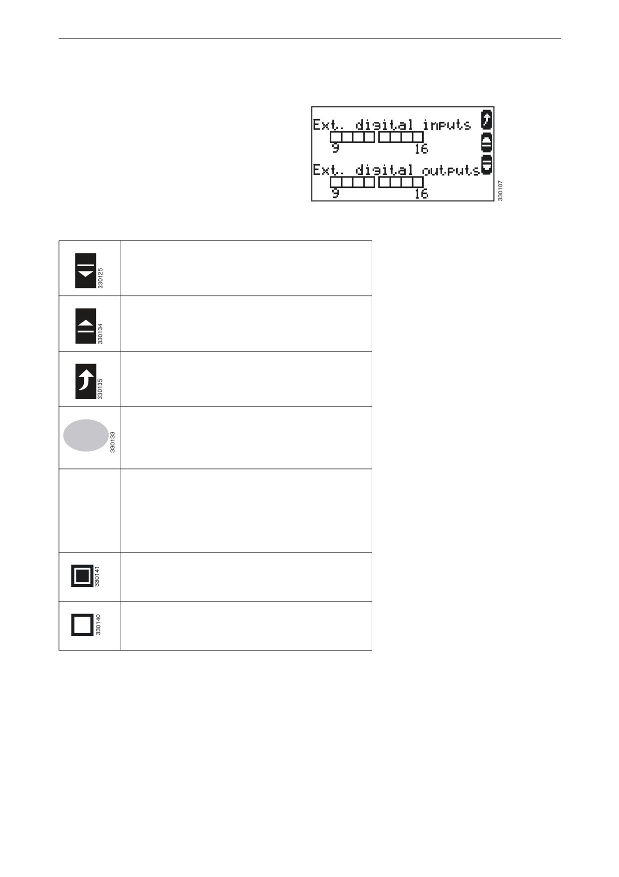
Digital inputs and outputs 9-
16
This view is available in all operating modes.
This view is displayed when the display button
for next view is pressed if another external ex-
pansion board has been connected to the instru-
ment panel.
The status of digital inputs and outputs 9-16 is
displayed.
Digital inputs and outputs 9-16
Navigate to the next view.
Navigate to the previous view.
Return to the Home view.
Switch to operating mode stop.
STOP
Displays the status of digital inputs and outputs 9-16.
The configuration of the input determines how the
instrument panel reacts. If the input is configured as
normally open it will react when it is energised. If the
input is configured as normally closed it will react
when it is de-energised.
Displays that a digital input is energised or that a dig-
ital output is active.
Displays that a digital input is de-energised or that a
digital output is inactive.
17
Display navigation
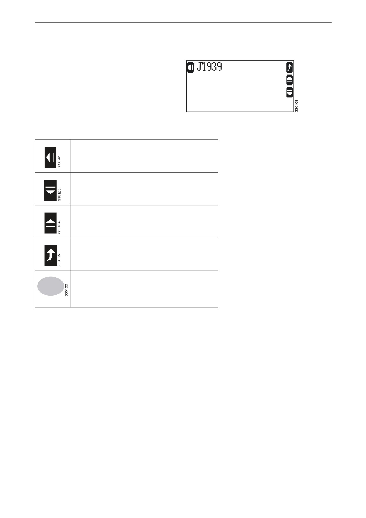
J1939
This view is available in all operating modes.
This view is displayed when the display button
for next view is pressed if a control unit is con-
figured.
This allows access to a submenu that displays a
list of messages from the instrument panel ac-
cording to the J1939 standard for CAN commu-
J1939
nication.
Go to the display of messages from the instrument
panel.
Navigate to the next view.
Navigate to the previous view.
Return to the Home view.
Switch to operating mode stop.
STOP
18
Display navigation
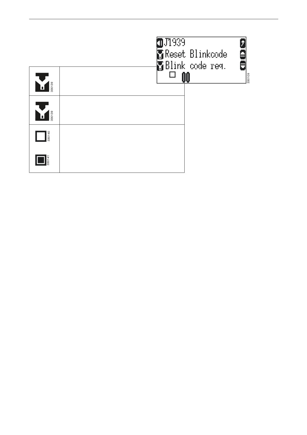
If the parameters ECU remote controlled and
Device type are configured to S6 Scania this
view is displayed.
Reset instrument panel flash codes.
J1939
Display instrument panel flash codes.
Indicate the flash code visually.
19
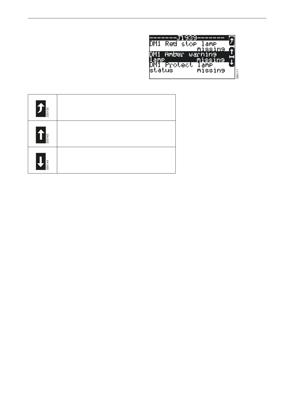
Display navigation
Messages from J1939
This view is available in all operating modes.
This view is displayed when the display button
on the top left of the J1939 view is pressed.
All messages that have been sent from the instru-
ment panel are displayed.
Messages from J1939
Return to the J1939 view.
Scroll up to the previous message.
Scroll down to the next message.
20

Display navigation
Time and date
This view is available in all operating modes.
This view is displayed when the display button
for next view is pressed.
The date and time are displayed.
Date and time
Navigate to the next view.
Navigate to the previous view.
Return to the Home view.
21
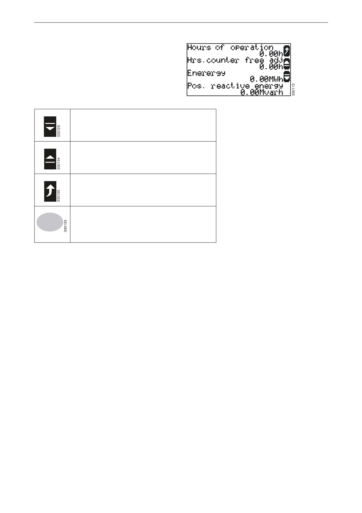
Display navigation
Counter
This view is available in all operating modes.
This view is displayed when the display button
for next view is pressed.
All counters are displayed.
Counter
Navigate to the next view.
Navigate to the previous view.
Return to the Home view.
Switch to operating mode stop.
STOP
22
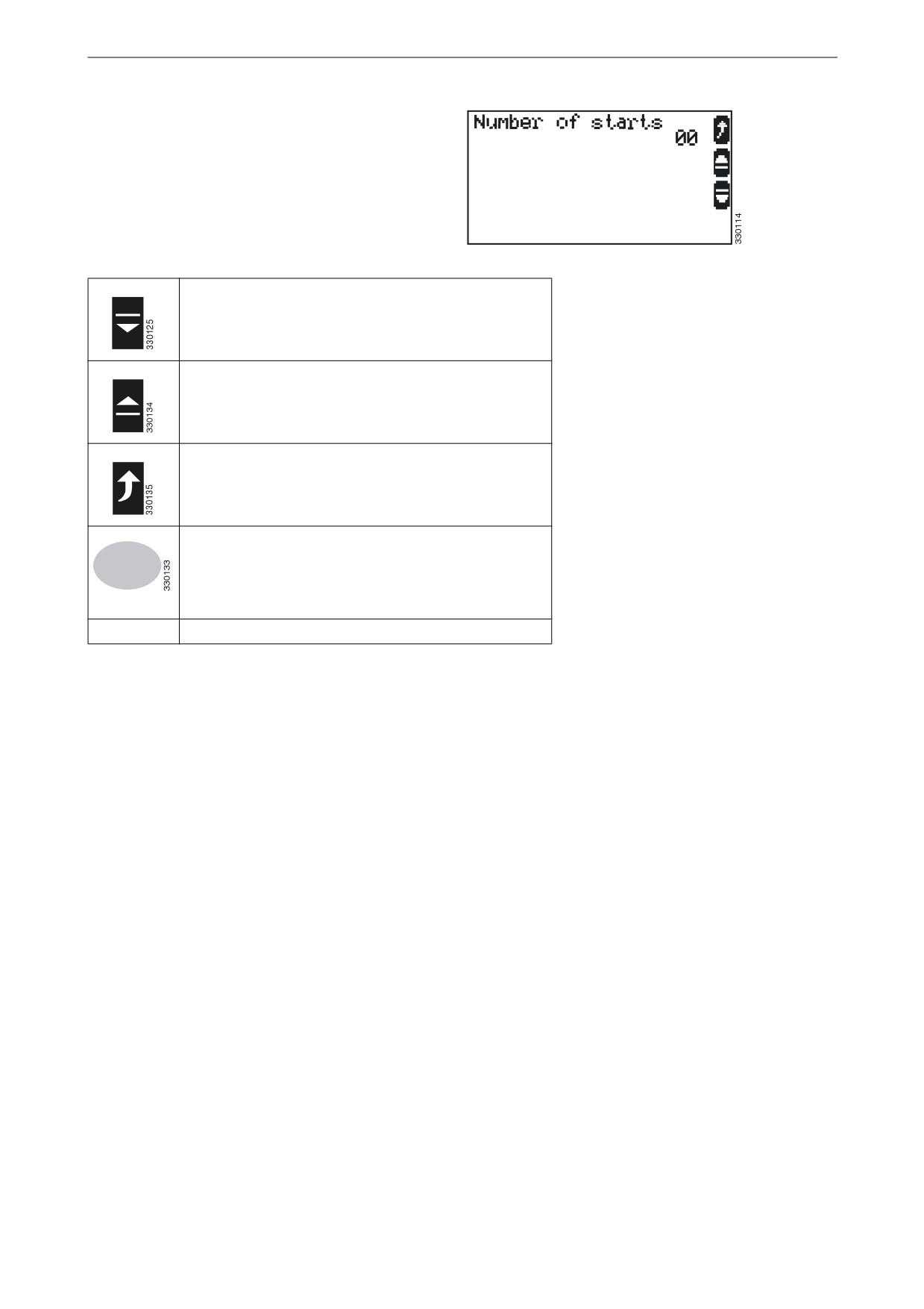
Display navigation
Start counter
This view is available in all operating modes.
This view is displayed when the display button
for next view is pressed.
The counter displays the total number of starts.
Start counter
Navigate to the next view.
Navigate to the previous view.
Return to the Home view.
Switch to operating mode stop.
STOP
00
Total number of starts
23
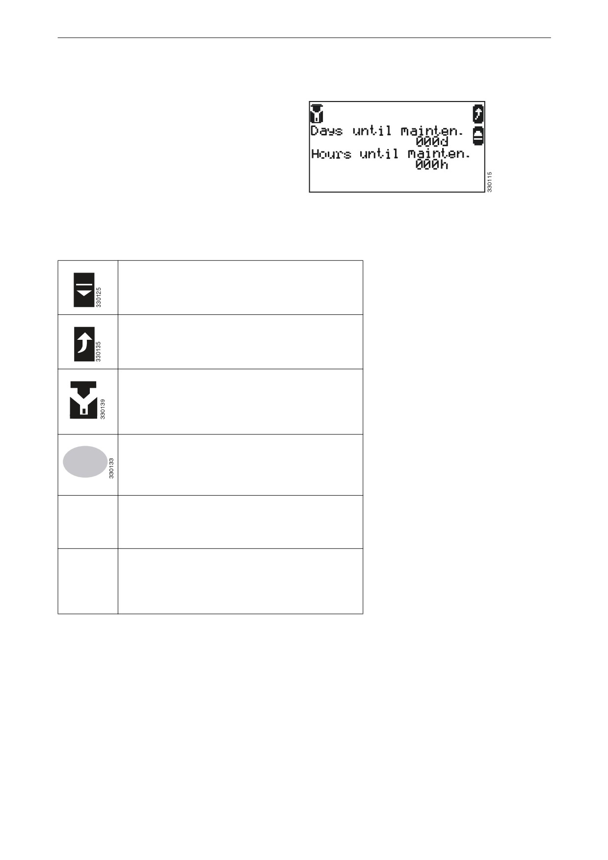
Display navigation
Inspection indicator
This view is available in all operating modes.
This view is displayed when the display button
for next view is pressed.
The days/hours remaining until the next inspec-
tion are displayed.
If the date of the inspection has passed Mainte-
nance overdue xxxd/xxxh is displayed.
Inspection indicator
A maximum of 999 days/999 hours since inspec-
tion are displayed.
Navigate to the previous view.
Return to the Home view.
Navigate to the Maintenance Reset view to reset the
day and hour counters to the configured inspection
intervals. The function is only available if the param-
eter Code level for reset maintenance is configured to
the necessary access level.
Switch to operating mode STOP.
STOP
Days until
Days remaining until the next inspection. When the
mainten.
day counter reaches 000 an alarm message, to inspect
000d.
the generator set, is sent. Reset the day counter when
the requested inspection has been performed.
Hours until
Hours remaining until the next inspection. When the
mainten.
time counter reaches 000 an alarm message, to
000h
inspect the generator set, is sent. Reset the day coun-
ter when the requested inspection has been per-
formed.
24
Display navigation
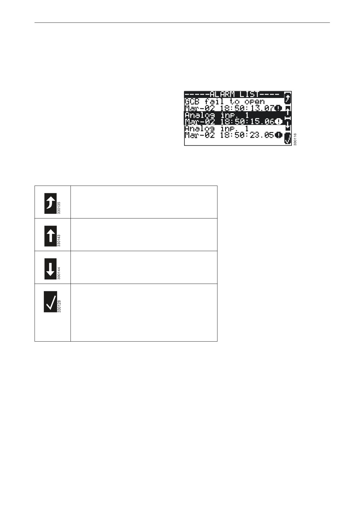
Alarm messages
This view is available in all operating modes.
This view is displayed when the display button
with the exclamation mark symbol on the home
view is pressed.
Displays all the alarm messages that have not
been acknowledged.
Each alarm message is displayed on two rows.
The first row contains the alarm message and the
second row displays the date and time of the
alarm in the format month-day-hour-minute-sec-
ond.
Alarm messages
The exclamation mark symbol indicates that the
cause of the alarm persists.
Return to the Home view.
Scroll up to the next alarm message.
Scroll down to the next alarm message.
Acknowledge the selected alarm message (inverted
display). This is only possible if the cause of alarm
no longer persists.
If an alarm cause persists, and the alarm indicator
lamp is flashing, the alarm signal is interrupted and
the alarm is marked as acknowledged.
25

The four sub views of the display
The four sub views of the
display
The display is divided into four sub views: Val-
ues, Softkeys, Messages and Operation.
Values
Softkeys
Messages
Operation
The four sub views of the display
Measured values
The Values sub view displays voltages, frequen-
cies and outputs.
Measured values
Messages
The Messages sub view displays all active alarm
messages and the current operating mode.
Messages
26
The four sub views of the display
Operation
The Operation sub view contains a line chart for
the application mode that shows the current sta-
tus of the circuit breaker in the automatic transfer
switch and in the generator set.
In this sub view there are display buttons for
manual operation of the generator set.
Operation
Display buttons
The Softkeys sub view allows navigation be-
tween views, levels and operating modes.
Display buttons
27
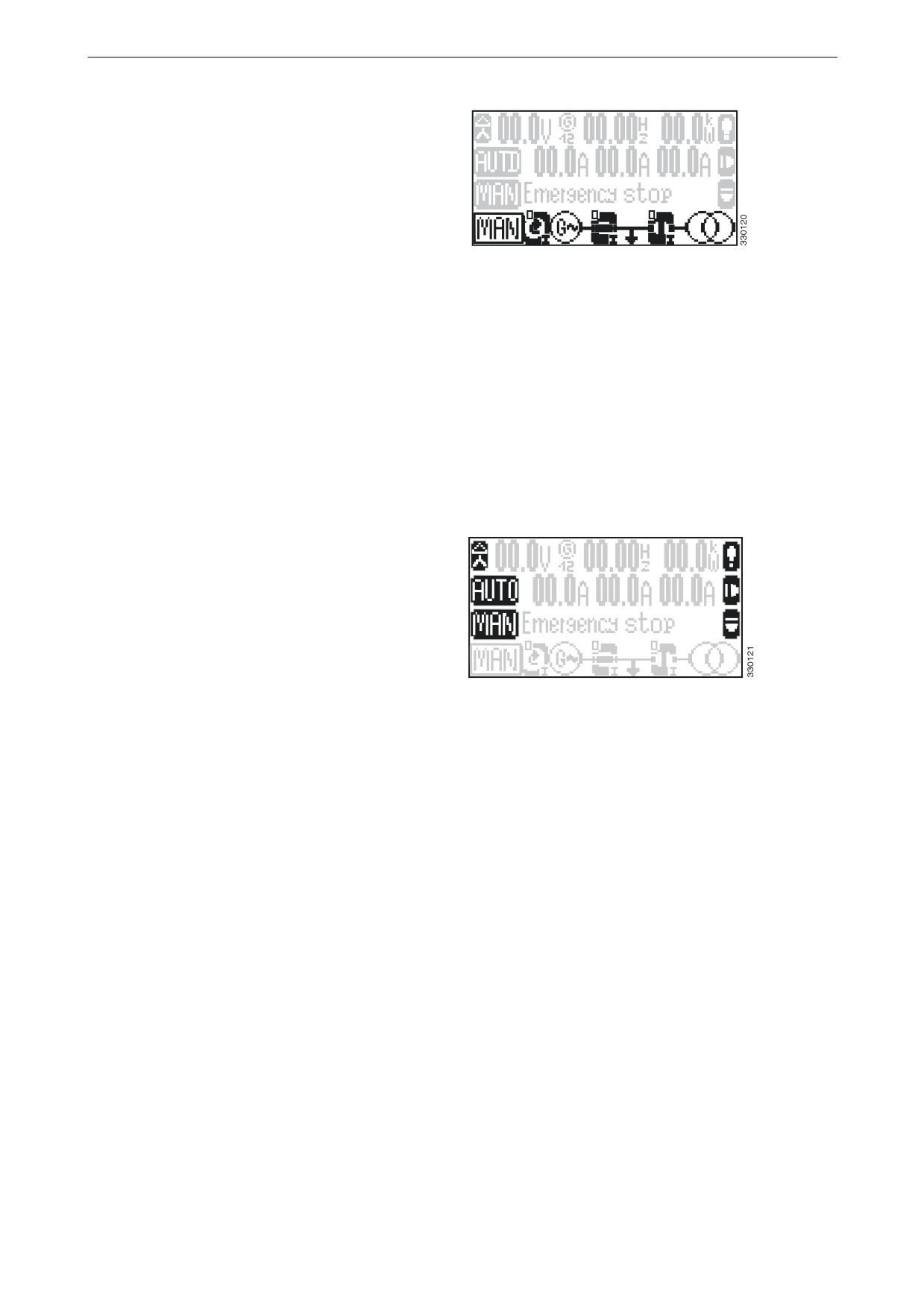
Operating modes
Operating modes
Display buttons for selecting
operating mode
Press one of the display buttons AUTO, MAN or
STOP to select operating mode.
Depending on the selected application, various
display buttons are activated or deactivated.
If stop operating mode is selected, the indicator
lamp next to the switch is on.
Note:
If the instrument panel is configured so that only
one operating mode is possible, these display
buttons are not displayed and the operating mode
Display buttons for selecting operating mode
cannot be changed.
Stop operating mode
When stop operating mode has been selected the
generator set engine is switched off.
Automatic operating mode
In automatic operating mode all functions for the
engine and for the circuit breaker in the generator
set and in the automatic transfer switch are car-
ried out automatically by the instrument panel.
The function of the instrument panel depends on
its configuration and how external signals are
processed.
Example of a typical
line chart
The following states are indicated in the line
chart.
Engine
The engine is switched off.
28

Operating modes
The engine is running.
Generator
The generator protection is not active
(engine protection delay).
The generator is not delivering volt-
age.
The generator is delivering voltage
within limits.
Circuit breaker in the
The circuit breaker in the generator
generator set
set is closed.
The circuit breaker in the generator
set is open.
Busbar
The busbar is not live (deactivated).
The busbar is live (activated).
Circuit breaker in the
The circuit breaker in the automatic
automatic transfer
transfer switch is closed.
switch
The circuit breaker in the automatic
transfer switch is open.
Electrical power net-
The ordinary electrical power net-
work
work is not delivering voltage.
The ordinary electrical power net-
work is delivering voltage within
limits.
29

Operating modes
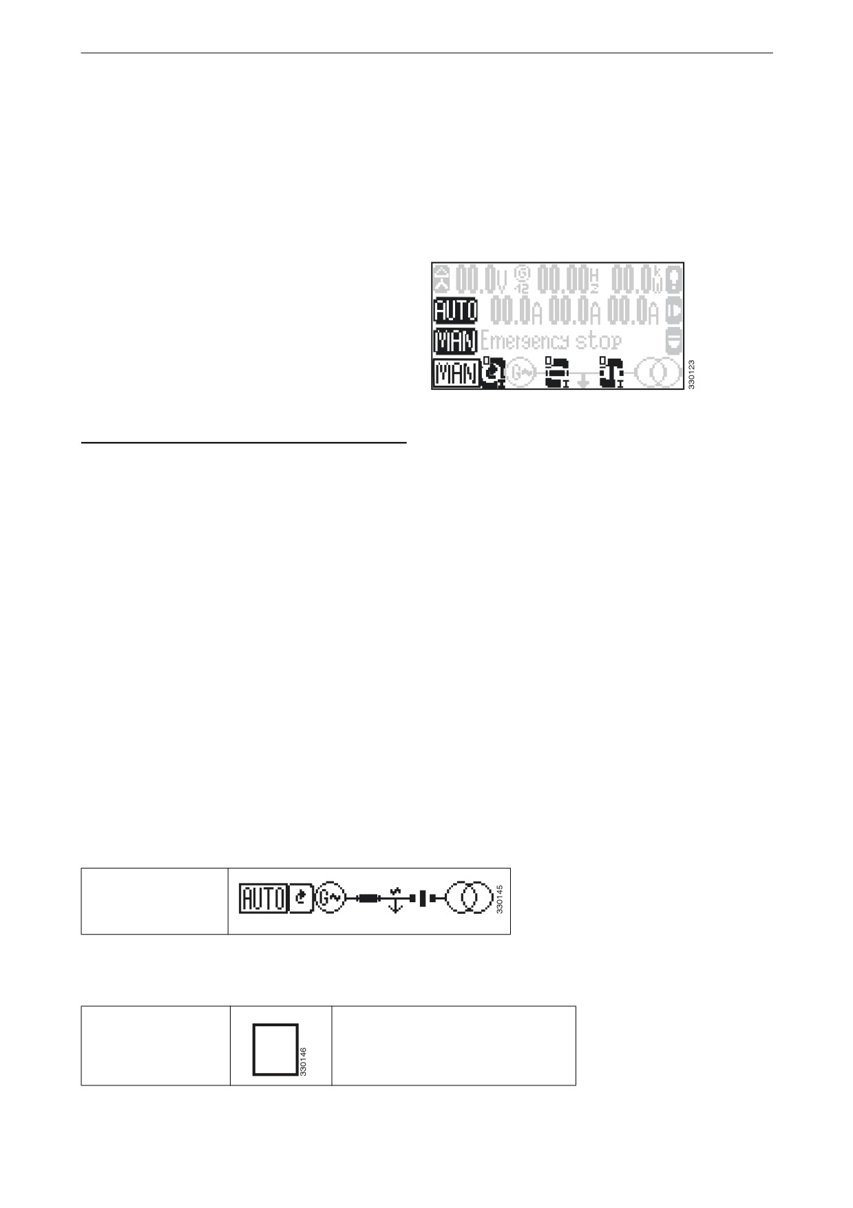
Manual operating mode
In manual operating mode the display buttons
are activated for manual operation of the genera-
tor set and the circuit breakers in the automatic
transfer switch and generator set.
The symbols "0" and "I" indicate whether a start
or stop command is activated for the engine, and
whether an open or close command is activated
for each circuit breaker.
Manual operating mode
Engine
Press the left-hand display button to start the en-
gine.
• If the engine starts, the arrow in the display
button rotates, the ~ symbol is displayed to
the right of the G symbol and the gap in the
circle around the G symbol closes when de-
layed engine monitoring has been completed.
• If the engine does not start, the I symbol
flashes during startup.
Press the left-hand display button to shut down
the engine.
• If the engine is stopped "0" is displayed con-
tinuously, the rotating arrow and the ~ sym-
bol disappear and the gap in the circle around
the G symbol returns.
• If the engine is not stopped the arrow in the
display button continues to rotate, the ~ sym-
bol is displayed and "0" continues to flash for
as long as a voltage is being detected.
Circuit breakers in the generator set
and automatic transfer switch re-
spectively
Press the display button under the desired circuit
breaker (in the generator set or in the automatic
transfer switch) when the symbol is vertical to
close the circuit.
• If the circuit closes, the symbol rotates hori-
zontally and "I" is displayed continuously in
the display button.
• If the circuit does not close, the symbol re-
mains vertical and "I" continues to flash in the
display button until the circuit closes.
Press the display button under the desired circuit
breaker (in the generator set or in the automatic
transfer switch) when the symbol is horizontal to
open the circuit.
30
Operating modes
• If the circuit opens the symbol rotates verti-
cally and "0" is displayed continuously in the
display button.
• If the circuit does not open the symbol re-
mains horizontal and "0" continues to flash in
the display button until the circuit opens.
31