Scania 4000 Instrumentation en-GB 2 268 463. Operator’s manual - part 1

Operator's manual
4000
Instrumentation
en-GB 2 268 463
Issue 1.0
Preface
3
Functions
3
Instrument panel
5
Display navigation
6
Overview of measured values for the generator6
Overview of measured values for the electrical
power network
8
Detailed measured values for the generator . 10
Detailed measured values for the electrical pow-
er network
11
Monitored current
13
Detailed analogue input measured values . . . 14
Digital inputs and outputs
15
Digital inputs and outputs 1-8
16
Digital inputs and outputs 9-16
17
J1939
18
Messages from J1939
20
Time and date
21
Counter
22
Start counter
23
Inspection indicator
24
Alarm messages
25
The four sub views of the display
26
Measured values
26
Messages
26
Operation
27
Display buttons
27
Operating modes
28
Display buttons for selecting operating mode28
Stop operating mode
28
Automatic operating mode
28
Manual operating mode
30
Components in the central electric unit
32
2
Preface
Preface
This Operator’s manual describes operation of
instrument panel 4000. The information was cor-
rect at the time of going to press. Scania reserves
the right to make alterations without prior notice.
Note:
This Operator’s manual describes a generator set
that is equipped with all available options. Ignore
inputs and outputs, functions, views and other
details not found on your generator set.
This Operator’s manual is for guidance only; this
is because the large number of parameter settings
does not make it possible to describe every pos-
sible combination.
Note:
Always use Scania spare parts for repair work.
Functions
Instrument panel 4000 is a microcontroller-
based instrument panel used to start and stop the
generator set manually or automatically via an
external signal.
The instrument panel runs and monitors parame-
ters to ensure trouble-free operation of the gener-
ator set. The instrument panel display displays
the operational status and display messages.
Instrument panel 4000 has the following func-
tions:
• Operates the generator set.
• Protects the engine and generator.
• Measures engine data: oil pressure and tem-
perature, coolant temperature, battery volt-
age, engine speed, inspection etc.
• Measures generator data: voltage, current,
power, etc.
• Starts the engine.
• Displays alarms, trips the miniature circuit
breakers and switches off the engine.
• With the generator set in standby mode: start-
ing the generator set automatically when a
power failure is detected on the electrical
power network.
3
Functions
• Communicating with the engine control unit
via CAN for diagnostics and prognostics.
4
Instrument panel
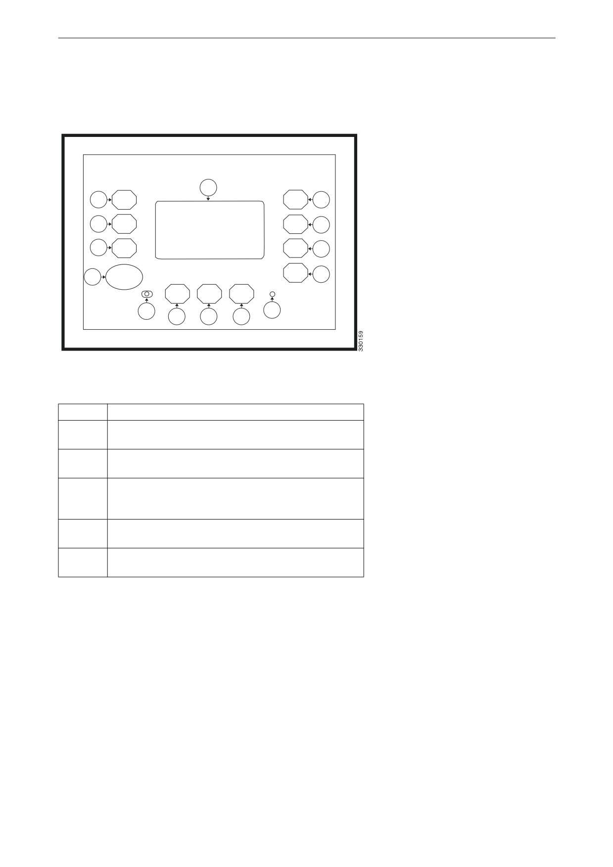
Instrument panel
The illustration below displays the instrument
panel with switches, indicator lamps and display.
12
1
5
2
6
3
7
4
STOP
8
13
14
9
10
11
Item
Function
1-3 and
Display buttons with functions dependent on the oper-
5-11
ating mode selected.
4
The STOP switch is always active and switches off the
generator set engine when it is pressed.
12
The display contains display buttons and displays
measured values, operating mode and display mes-
sages.
13
The left-hand indicator lamp indicates that the instru-
ment panel is in operating mode stop.
14
The right-hand indicator lamp indicates that there are
alarm messages in the instrument panel.
5

Display navigation
Display navigation
The information content comprises different
views.
The display buttons that are available in each
view are described below.
Overview of measured values
for the generator
This view is displayed on start up and is availa-
ble in all application modes.
The generator symbol G located at the top of the
display in front of the frequency value, indicates
that the generator measured values are being dis-
played.
Navigate to the next view.
Generator measured values
Display the main menu.
Display generator voltages (between phases and
between phase and neutral conductor).
Display unacknowledged alarm messages.
Acknowledge display messages and cancel the alarm
signal. Only displayed if the alarm indicator lamp is
flashing.
Start or switch off the engine. Only displayed in man-
ual operating mode.
Open or close the circuit breaker in the generator set
or in the automatic transfer switch. Only displayed in
manual operating mode.
6

Display navigation
Switch to automatic operating mode.
Switch to manual operating mode.
Switch to operating mode stop.
STOP
7

Display navigation
Overview of measured values
for the electrical power net-
work
This view is only available in the application
modes that include the opening and closing of
the circuit breaker in the generator set and in the
automatic transfer switch.
This view is displayed when the display button
for next view is pressed.
The network symbol, which is located at the top
of the display in front of the frequency value, in-
dicates that the network measured values are be-
ing displayed.
Measured values for the electrical power network
Navigate to the next view.
Navigate to the previous view.
Display mains voltages (between phases and between
phase and neutral conductor).
Display unacknowledged alarm messages.
Start or switch off the engine. Only displayed in man-
ual operating mode.
Open or close the circuit breaker in the generator set
or in the automatic transfer switch. Only displayed in
manual operating mode.
Switch to automatic operating mode.
Switch to manual operating mode.
8

Display navigation
Switch to operating mode stop.
STOP
9

Display navigation
Detailed measured values for
the generator
This view is available in all application modes.
This view is displayed when the display button
for next view is pressed.
All generator measured values are displayed.
Note:
The view may deviate from this example (3-
phase with neutral conductor), depending on the
Detailed measured values for the generator
configured system.
Navigate to the next view.
Navigate to the previous view.
Return to the Home view.
Switch to operating mode stop.
STOP
1/2/3
Displays generator voltages VL1N/VL2N/VL3N and
generator currents IL1/IL2/IL3.
12/23/31
Displays generator voltages VL12/VL23/VL31.
00.00Hz
Displays generator frequency.
000kW
Displays actual generator output.
000kvar
Displays reactive generator output.
1.00
Displays generator output factor = 1.
Lg0.00
Displays generator output factor (inductive load).
Ld0.00
Displays generator output factor (leading).
Displays the phase rotation clockwise.
Displays the phase rotation anticlockwise.
10

Display navigation
Detailed measured values for
the electrical power network
This view is only available in the application
modes that include the opening and closing of
the circuit breaker in the generator set and in the
automatic transfer switch.
This view is displayed when the display button
for next view is pressed.
All network measured values are displayed.
Note:
The view may deviate from this example (3-
phase with neutral conductor), depending on the
Detailed measured values for the electrical power
configured system.
network
Navigate to the next view.
Navigate to the previous view.
Return to the Home view.
Switch to operating mode STOP.
STOP
1/2/3
Displays mains voltages VL1N/VL2N/VL3N and pro-
spective currents IL1/IL22/IL3.
12/23/31
Displays mains voltages VL12/VL23/VL31.
00.00Hz
Displays mains frequency.
000kW
Displays actual mains output.
000kvar
Displays reactive mains output.
1.00
Displays generator output factor = 1.
Lg0.00
Displays generator output factor (inductive load).
Ld0.00
Displays generator output factor (leading).
Displays the phase rotation clockwise.
11

Display navigation
Displays the phase rotation anticlockwise.
12

Display navigation
Monitored current
This view is available in all operating modes.
This view is displayed when the display button
for next view is pressed.
The value to the right of the arrow symbol dis-
plays the maximum current measured by the in-
strument panel.
If the instrument panel is configured to monitor
Monitored current
ground current no network current value is dis-
played here.
Navigate to the next view.
Navigate to the previous view.
Return to the Home view.
The actual measured value is displayed to the left of
the arrow symbol. The maximum measured value is
displayed to the right of the arrow symbol.
Zero the maximum measured value.
Switch to operating mode stop.
STOP
1/2/3
Displays generator currents IL1/IL2/IL3 and network
current IL.
13

Display navigation
Detailed analogue input
measured values
This view is available in all operating modes.
This view is displayed when the display button
for next view is pressed.
The analogue input measured values are dis-
played graphically and numerically.
Detailed analogue input measured values
Navigate to the next view.
Navigate to the previous view.
Return to the Home view.
Switch to operating mode stop.
STOP
14

Display navigation
Digital inputs and outputs
This view is available in all application modes.
This view is displayed when the display button
for next view is pressed.
The status of digital inputs and outputs is dis-
played.
Digital inputs and outputs
Navigate to the next view.
Navigate to the previous view.
Return to the Home view.
Switch to operating mode stop.
STOP
Displays the status of digital inputs and outputs.
The configuration of the input determines how the
instrument panel reacts. If the input is configured as
normally open it will react when it is energised. If the
input is configured as normally closed it will react
when it is de-energised.
Displays that a digital input is energised or that a dig-
ital output is active.
Displays that a digital input is de-energised or that a
digital output is inactive.
15