Scania DI16 PDE. Marine engine en-GB 2 805 697. Operator’s manual - part 6
Miscellaneous
Miscellaneous
3
2
Checking the drive belt
5
IMPORTANT!
2
Before starting, make a note of how the drive belt
is fitted. Refit the drive belt with the same direc-
tion of rotation as it had before removal.
4
1. Check the drive belt for cracks. Renew the
drive belt if deep cracks have formed.
1
Note:
Small and shallow cracks are normal and form
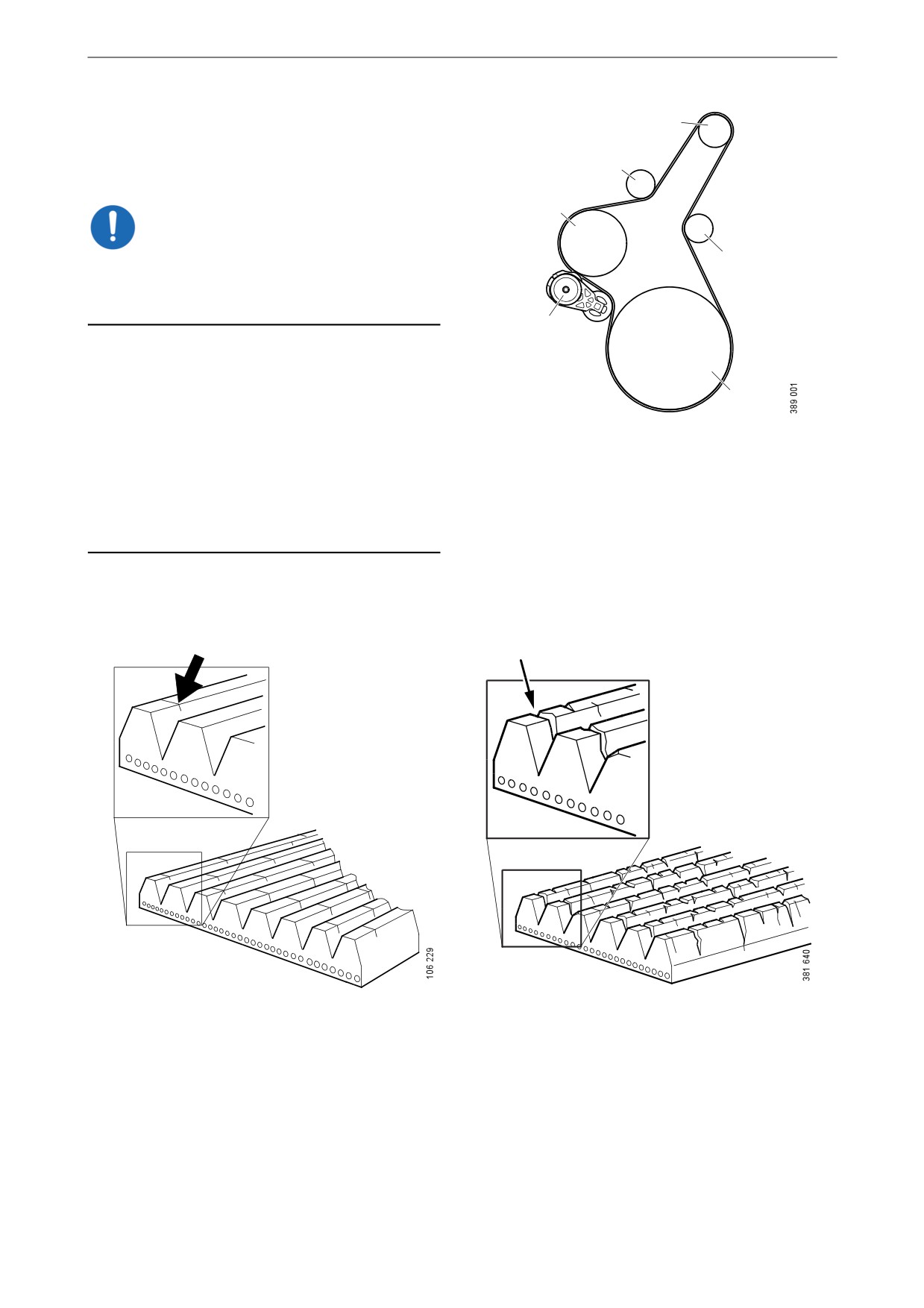
Example of a drive belt.
after only a few hours of operation. They do not
1. Crankshaft.
mean that the drive belt needs to be renewed. If
2. Idler roller.
there are many deep cracks, or if parts of the
3. Alternator.
drive belt have started to come off, the drive belt
4. Belt tensioner.
must then be renewed.
5. Coolant pump.
Example of a minor crack in the drive belt. The drive
The drive belt has deep cracks and must be renewed.
belt can be refitted.
80

Miscellaneous
2. Check drive belt wear. Renew the drive belt
if it is too worn.
The drive belt is starting to become worn, but can be
The belt is worn down to the cord. The drive belt
refitted.
must be renewed.
Checking for leaks
IMPORTANT!
If serious leakage occurs, contact your nearest
workshop.
1. Start the engine.
2. Check for oil, coolant, fuel, air or exhaust
leaks.
3. Tighten or renew leaking connections.
Check the overflow holes which show
whether the O-rings between the cylinder
liners and crankcase are leaking.
4. Check whether the drain hole on the coolant
pump is blocked. If there is a leak, renew the
seal in the pump or the complete coolant
pump.
81
Miscellaneous
Checking and adjusting the
valve clearance and unit in-
jectors
Special tools
Number
Designation
Illustration
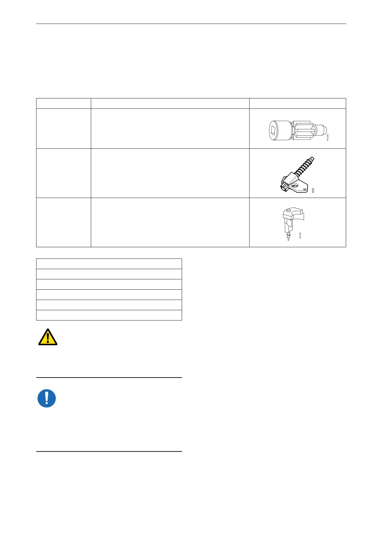
99 309
Turning tool for rotating the flywheel from below
2 402 509
Turning tool for rotating the flywheel from above
99 442
Setting tool
Other tools
Torque wrench, 0-50 Nm
Waterproof felt-tip pen
0.45 and 0.70 mm feeler gauges
Flash light
Mirror
WARNING!
Block the starting device or remove a battery ca-
ble. If the engine starts unexpectedly, there is a
serious risk of injury.
IMPORTANT!
The engine must be cold when the work is car-
ried out.
Remember to remove the turning tool from the
flywheel after adjustment.
Note:
Carry out the working without pausing, so that
no step is overlooked.
82
Miscellaneous
Carry out a check and adjustment of the valve
clearances and the unit injectors one more time
after the first 500 hours of operation. After this,
adjustment according to the regular interval
takes place, which is every 2,000 operational
hours.
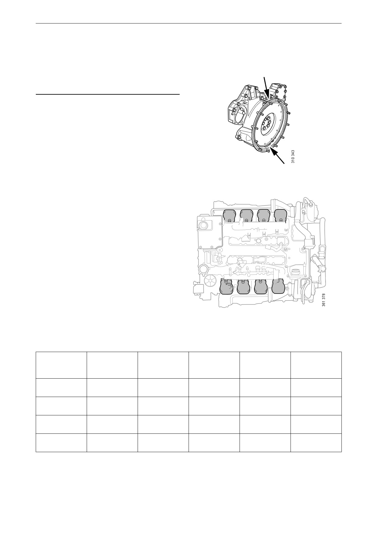
On the flywheel is engraved the reference infor-
mation UP TDC, DOWN TDC and the angle in-
dications listed in the table below. Depending on
the engine installation and type of flywheel
housing, this information is visible in one of the
windows, either furthest up or furthest down on
the flywheel. See illustration.
Upper and lower window to read the engraving on
the flywheel.
1
2
3
4
Workflow table
Adjust valves and injectors according to the table
below. Follow the respective column depending
on whether you are reading the engraving on the
flywheel in the lower or the upper window. Start
adjustment at the top of the table.
5
6
7
8
Order of cylinders.
Reading in the
Valve transi-
Adjust intake
Adjust exhaust
Adjust injector
Reading in the
lower window
tion on cylinder
valve on cylin-
valve on cylin-
on cylinder
upper window
der
der
DOWN TDC
6
7 and 8
4 and 5
4 and 5
UP TDC (180°)
(0°)
UP TDC (180°)
7
1 and 5
2 and 6
2 and 6
DOWN TDC
(0°)
DOWN TDC
1
2 and 4
3 and 7
3 and 7
UP TDC (540°)
(360°)
UP TDC (540°)
4
3 and 6
1 and 8
1 and 8
DOWN TDC
(360°)
83
Miscellaneous
Checking and adjusting the valve
clearance
Valve clearance, specifications
Intake valve
0.45 mm (0.018 in)
Exhaust valve
0.70 mm (0.028 in)
Tightening torques
Lock nut for valves
35 Nm (26 lb/ft)
1. Clean the rocker covers and the area around
them.
2. Remove the rocker covers.
3. Use the turning tool appropriate to the instal-
lation of the engine. Tool 99 309 is used to
rotate the flywheel from the underside of the
engine and tool 2 402 509 is used from the
top side.
4. Start adjusting one cylinder according to the
table. Rotate the flywheel until the correct
engraving can be read on the flywheel. It
may be necessary to rotate it more than 1 rev-
olution.
Rotate the flywheel in the rotational direc-
tion of the engine, which is clockwise
viewed from the front of the engine and anti-
clockwise viewed from the back of the en-
gine.
During a valve transition, the exhaust valve
(the long arm) is closing at the same time as
the intake valve is opening.
The UP TDC engraving on the flywheel is
now visible in the window furthest up on the
flywheel. The DOWN TDC engraving is vis-
ible in the lower window.
5. Read Workflow table on the previous page to
3
see which valve to adjust.
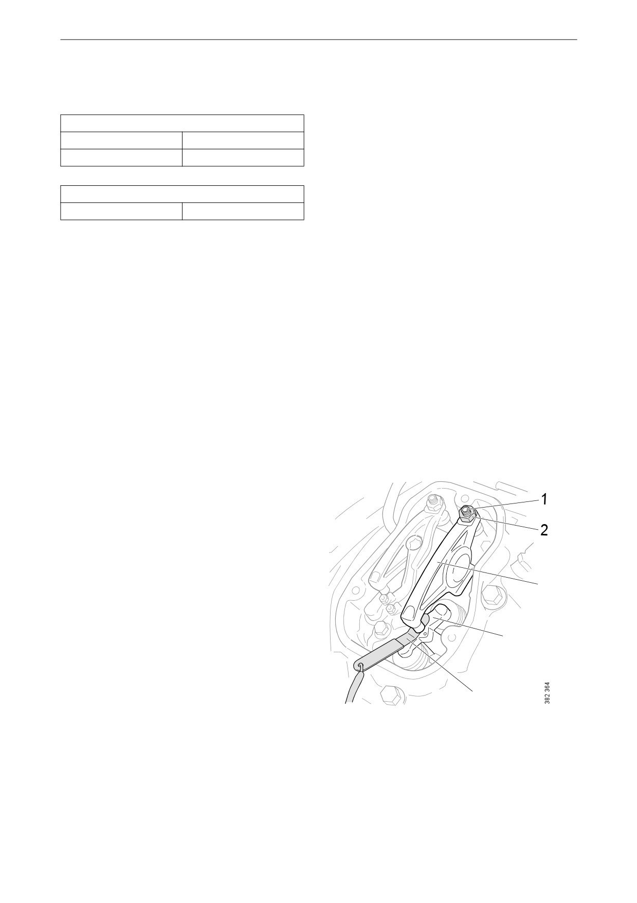
6. Stick the feeler gauge under the pressure pad
of the rocker arm and check the valve clear-
4
ance.
7. If necessary, adjust the valve clearance by
a) loosening the lock nut on the end of the
rocker arm
5
b) adjusting the valve clearance with the ad-
justing screw
1.
Adjusting screw.
c) tightening the lock nut.
2.
Lock nut.
8. Mark the rocker arm with the felt-tip pen and
3.
Rocker arm.
adjust the unit injector according to the next
4.
Valve bridge.
section. Then continue on to the next cylin-
5.
Feeler gauge.
der according to the table.
84

Miscellaneous
Checking and adjusting the unit in-
jectors
Tightening torques
Lock nut for unit injec-
39 Nm (29 lb/ft)
tors
1. See the Workflow table for details of the in-
jectors to be adjusted.
2. Fit the setting tool with the metal plate
around the unit injector.
The unit injector is correctly set when the
3
2
small piston (1) is level with the flat upper
surface of the tool. Use a finger to check.
You can feel very small differences. See also
the illustrations on the next page.
3. If necessary, adjust the unit injector by
a) loosening the lock nut (2)
b) adjusting the unit injector using the adjust-
ing screw (3)
c) tightening the lock nut.
IMPORTANT!
Remove the setting tool when the adjustment is
done.
4. Mark the injector with the felt-tip pen and
1
continue adjustment according to the table.
85
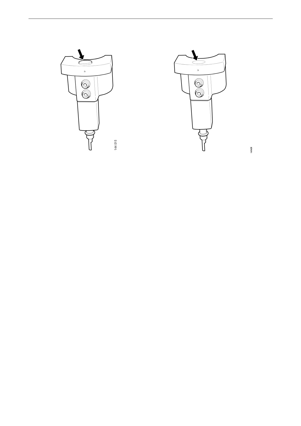
Miscellaneous
The setting tool piston is above or below the flat
The setting tool piston is level with the flat upper
upper surface of the tool. Adjust the unit injector. surface of the tool. The unit injector is correctly
adjusted.
86
Miscellaneous
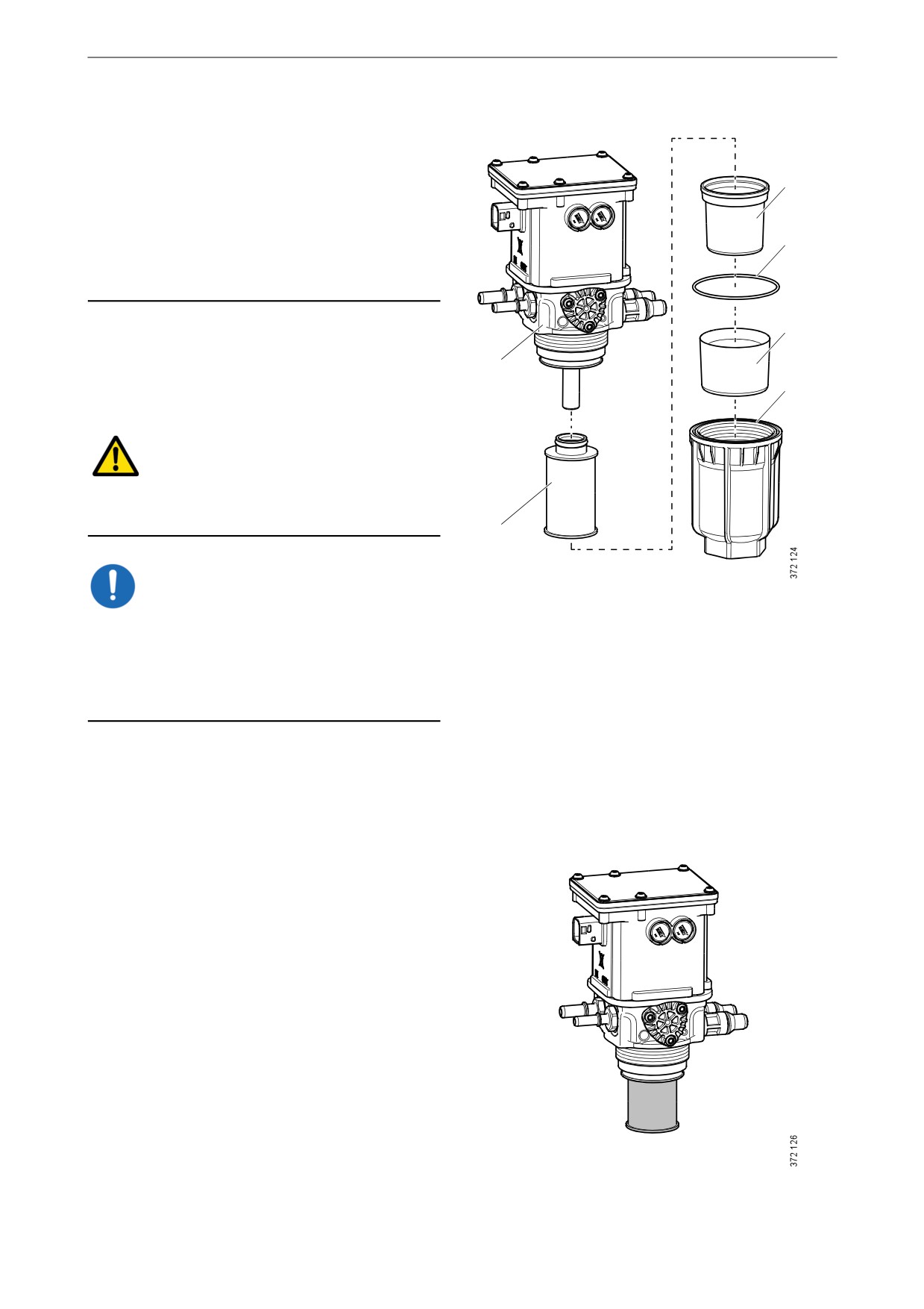
Renewing the reductant fil-
ters
Note:
3
There is always one reductant pump with a filter
in the reductant tank (buffer tank). However,
there may be an additional reductant pump with
4
a filter between the main reductant tank and the
buffer tank.
5
1. Wipe clean around the filter housing to pre-
vent impurities from penetrating it.
1
2. Remove the filter housing. Use a 46 mm
6
socket.
WARNING!
There may be a lot of reductant in the filter hous-
ing and it may spill out. Wear protective gloves.
2
IMPORTANT!
1.
Reductant pump.
Always rinse away reductant spillage on connec-
2.
Filter.
tions and other parts with lukewarm water to pre-
3.
Sealing diaphragm.
vent corrosion. If reductant seeps into electrical
4.
O-ring.
connections or electrical cables, these must be
5.
Antifreeze.
renewed.
6.
Filter housing.
3. Remove the sealing diaphragm.
4. Remove the old reductant filter and fit a new
one.
87

Miscellaneous
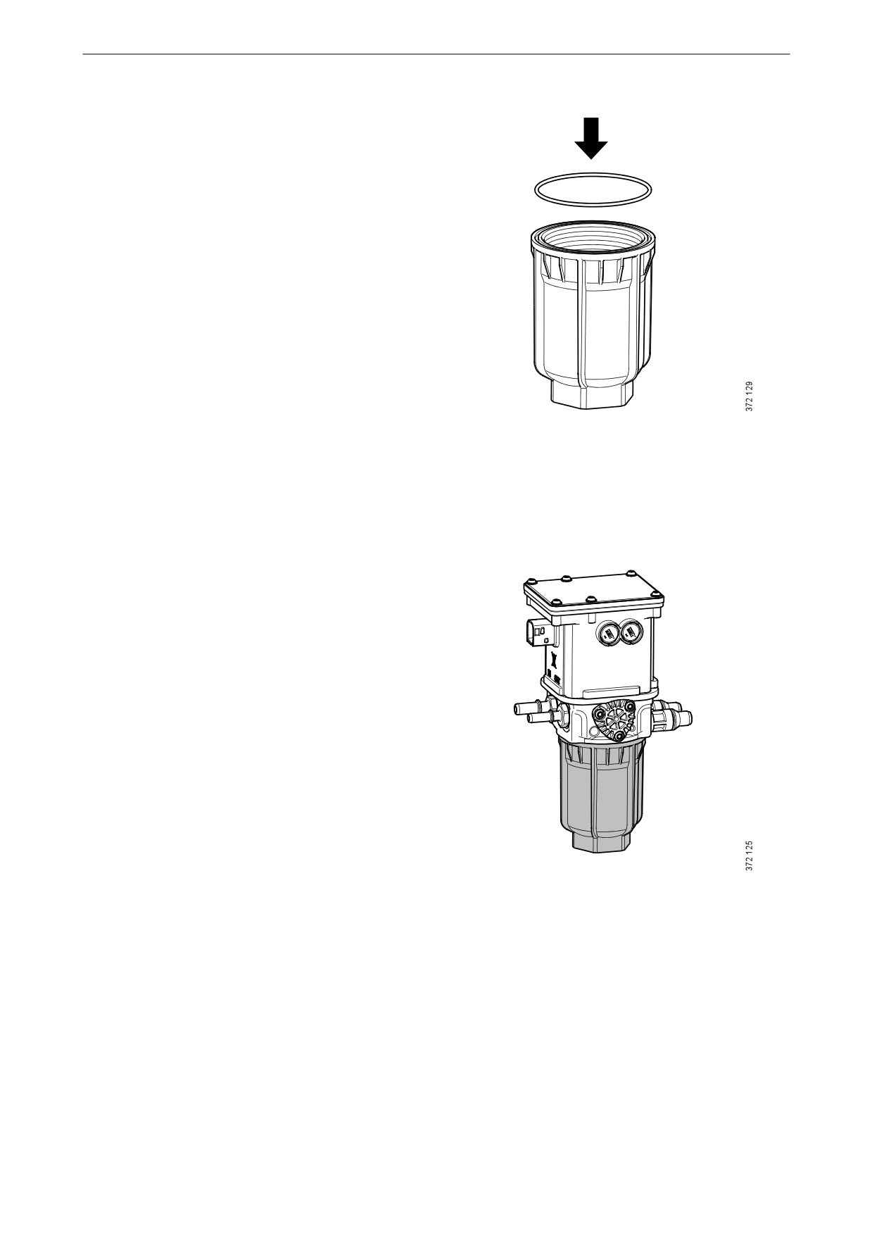
5. If the anti-freeze protection in the filter hous-
ing comes loose, wipe both the anti-freeze
protection and filter housing thoroughly so
that they are completely dry before they are
assembled again.
6. Wipe the sealing diaphragm and fit it over
the filter.
Ensure that the edge of the diaphragm is sit-
ting in the groove.
7. Lubricate the sealing diaphragm and threads
with the accompanying spray.
88
Miscellaneous
8. Renew the O-ring. Place the new O-ring in
the filter housing.
9. Refit the filter housing. Use a 46 mm socket.
Tighten to 80 Nm (59 lb-ft).
89

Quality requirements for fuel
phur content is used, it can cause damage to the
Quality requirements for
engine and the SCR system.
fuel
Quality requirements and testing standards for
the most important properties of different types
of fuel are described in the Workshop Manual.
This can be ordered from Scania dealers or di-
rectly from Scania.
Diesel
Properties
The quality of the diesel is very important for the
operation and service life of the engine and the
fuel system, and also for the engine performance.
REQUIREMENT!
The diesel should comply with the requirements
of European standard EN590.
However, Scania accepts larger tolerances of
certain properties. Please see the table below.
Property
Requirements
Viscosity at 40°C
1.4-4.5 cSt
(104°F)
Density at 15°C (59°F)
0.79-0.87 kg/dm3
Ignitability (CET rating)
minimum 49
Lowest flashpoint
56°C (132°F)
Particulate contamina-
Classification 22/20/17
tion level
according to ISO 4406
Sulphur content
IMPORTANT!
The operator is responsible for using the correct
type of diesel to ensure that local laws are com-
plied with.
Important to use low sulphur diesel
For engines with SCR systems certified in ac-
cordance with IMO Tier III, it is important to use
low-sulphur diesel, to ensure that the engine
works correctly. If diesel with an excessive sul-
90

Quality requirements for fuel
Permitted sulphur content in diesel
Engine type
Max. sulphur content
Remark
Engines without SCR sys-
4,000 ppm (0.4%)
If the sulphur content is higher than 2,000 ppm, the
tem connected
oil change intervals must be halved. A higher sul-
phur content than 4,000 ppm is not permitted, since
this will result in engine damage.
Engines with SCR system
500 ppm (0.05%)
Scania strongly recommends that fuel with a max-
connected
imum sulphur content of 50 ppm is used if the en-
gine is run with an SCR system connected for
longer periods of time.
Diesel with a higher sulphur content than
500 ppm for engines with SCR systems
If diesel with a higher sulphur content than per-
mitted is used on a short-term basis, this will not
cause permanent damage to the SCR catalytic
converter. The SCR catalytic converter may,
however, require diesel with a low sulphur con-
tent for some time after this to regain its normal
efficiency.
If diesel with an excessive sulphur content is
used for a longer period, there is a risk that the
SCR catalytic converter will not work properly.
Temperature dependence of diesel
IMPORTANT!
Mixing kerosene or other paraffins with the die-
sel is prohibited. The injectors may be damaged.
It is not permissible to mix petrol with diesel. In
the long term petrol can cause wear in the injec-
tors and engine.
91
Quality requirements for fuel
At temperatures lower than those specified for
the diesel, paraffin wax may precipitate from the
diesel and block filters and pipes. The engine can
then lose power or stop.
The diesel is adapted for use in the specific cli-
mate of each country. If an engine is to be oper-
ated in a temperature zone with a temperature
lower than normal, first identify the temperature
properties of that particular diesel.
DMX and DMA diesel
IMPORTANT!
Use of DMX and DMA diesel is not permitted
for engines with SCR systems.
DMX and DMA diesels normally cause in-
creased wear on the injection system. As a result
of the high sulphur content in these types of die-
sel, the engine oil is also affected. The engine oil
must have as high a Total Base Number (TBN)
as possible.
REQUIREMENT!
For engines running on DMX and DMA diesels,
the engine oil must have a TBN of at least 12.
When the engine is taken into operation the en-
gine oil must be analysed every 50 hours to de-
termine the correct oil change interval. The oil
analysis must be carried out according to the in-
structions in the Oil analysis section in this Op-
erator's manual.
Bear in mind that the emission limit for the cur-
rent engine type may limit the maximum permit-
ted sulphur content of the diesel.
HVO
HVO is a synthetic diesel which is manufactured
through the hydrogenation of plants and animal
fats. To the user, HVO is reminiscent of diesel in
accordance with EN590, apart from HVO having
a somewhat lower density.
Scania approves the use of up to 100% HVO for
all engines in accordance with the European
standard EN 15940.
92
Quality requirements for fuel
Biodiesel (FAME)
Use of biodiesel
IMPORTANT!
For engines with SCR systems, a maximum of
10% mixture of biodiesel should be used.
Scania uses the term biodiesel to refer to a re-
newable diesel made from greases or oils and
methanol. The biodiesel should conform to the
requirements of European standard EN 14214 or
Brazilian standard ANP-45. For biodiesel in ac-
cordance with EN 14214 or ANP-45, the generic
term FAME is frequently used.
Normal diesel in accordance with EN 590 can
contain up to 7% biodiesel from the diesel sup-
plier. There are grades of diesel that comply with
EN 590 but contain a higher mixture of biodies-
el.
Scania approves up to a 10% mixture of biodies-
el for all engines.
For PDE engines, Scania allows usage of up to
100% in accordance with EN 14214 or ANP-45.
However, this does not apply to engines with the
SCR system, where only 10% is permitted.
Maintenance interval
IMPORTANT!
Make sure that maintenance intervals are differ-
ent when operating on diesel or biodiesel.
With a greater mixture of biodiesel than 10%, the
renewal intervals for the following are halved:
• Fuel filter.
• Oil filter.
• Engine oil.
93
Quality requirements for fuel
The viscosity grade of the engine oil should be
xW-40. xW-30 grade oils are unsuitable due to
the fuel dilution effect.
Check the engine oil level regularly. If the oil
level exceeds the maximum level, the oil must be
changed. Check the cause if the oil level exceeds
the maximum level and contact your nearest Sca-
nia workshop if you suspect a fault.
Storage of biodiesel
IMPORTANT!
Biodiesel must not be stored for more than 6
months.
Biodiesel has a maximum storage life of
6 months from the date of production to the ex-
piry date. The fuel is affected by light, tempera-
ture, water, etc. during storage, which affects the
fuel characteristics and durability.
Biodiesel also has lower stability against oxida-
tion than diesel. This can result in a thickening of
the fuel and blocking of parts of the fuel system,
e.g. the fuel filter. Bacterial growth can occur
when fuel is stored in tanks under unfavourable
conditions. Avoid storage in barrels or auxiliary
tanks, except when fuel turnover rates are high.
Check tank cleanliness whenever refuelling
takes place.
If the engine has been refuelled with biodiesel,
and is stationary for a long period, condensation
water can form in the fuel tank resulting in bac-
terial growth.
See also the section Preservative fuel.
94

Reductant for SCR
ageing process is accelerated by a high ambient
Reductant for SCR
temperature.
The reductant should be handled in accordance
IMPORTANT!
with the following shelf life recommendation.
The operator is responsible for using the correct
type of reductant to ensure that local laws are
complied with.
Constant ambient
Minimum shelf life in
storage temperature in
months according to
°C.
ISO 22241-3
AdBlue is a solution consisting of urea and wa-
ter, and is usually called AdBlue®, DEF, ARLA
≤10
36
32 or AUS 32/AUS 40, depending on the market.
≤25
18
If the engine is equipped with an SCR system,
≤30
12
the reductant is added to the exhaust gases up-
stream of the catalytic converter. This reduces
≤35
6
nitrogen oxide emissions. The SCR system can
>35
Significant loss of shelf
be used with either 32.5% or 40% by weight of
life: check each batch
urea.
before use
Reductant is normally colourless if no dye has
been added. It is not harmful to the skin. Nor is it
toxic in small quantities, but it tastes very un-
pleasant.
Reductant with 32.5% by weight of urea freezes
at approx. -11°C (12°F). With 40% by weight of
urea freezes at 0°C (32°F). When the solution
freezes, ice and urea always maintain the same
concentration. Always store the reductant at a
temperature of between 0°C and 30°C (32 to
86°F).
Reductant is highly corrosive. Therefore, rinse
any reductant spillage from connections and oth-
er details using lukewarm water. Water works
very well for cleaning purposes. Please use hot
water. If reductant seeps into electrical connec-
tions or electrical cables, these must be renewed.
Reductant has a low surface tension and rapidly
spreads over large areas, which then become
very slippery.
Reductant can dry out and form white or greyish
brown crystals or deposits that can be washed
away with warm water.
The risk of crystal formation increases with low
outdoor temperatures. When the outdoor temper-
ature is below -20°C (-4°F), reductant dosing is
switched off to avoid the risk of crystals forming
in the SCR system.
IMPORTANT!
The use of reductant that has aged can damage
important components in the SCR system. The
95