Scania DI16 PDE. Marine engine en-GB 2 805 697. Operator’s manual - part 5

Cooling system
5. Fit the charge air pipe and the hose clamps.
6. Fit the crankcase ventilation hose.
7. Fit the catwalk:
- Loosely fit the protective plate to the
charge air pipe. Tighten the screws later.
- Fit the protective casing. Tighten the
screws later.
- Fit the catwalk with screws.
- Tighten all screws. The protective plate
and protective casing must be tightened to
a tightening torque of 15 Nm (11 lb-ft).
64
Cooling system
Internal cleaning: Removing oil and
3. Fill the cooling system with clean hot water
grease in the cooling system
mixed with detergent 2 479 017. Detergent
2 479 017 must make up 5-10% (depending
on the degree of dirt) of the total coolant vol-
Environment
ume.
Use a suitable container. Used coolant must be
If detergent 2 479 017 is not available, use a
disposed of as specified in national and interna-
dishwasher detergent for household dish-
tional laws and regulations.
washers that does not foam. Concentration
1%.
4. Run the engine until it has reached operating
Always fit new thermostats and a new cover to
temperature for approximately 20-30 min-
the expansion tank after cleaning, as the oil in the
utes. Remember to switch on the cab heating
cooling system destroys the seals. If the engine is
system, if one is installed.
equipped with a coolant filter, also renew this fil-
5. Drain the cooling system.
ter.
6. Fill the cooling system with clean, hot water
It may be necessary to wash it multiple times if
and run the engine for about 20-30 minutes.
the cooling system is very dirty. One cause of
7. Repeat steps 3-6 if the cooling system is not
contamination can be that oil is lying on top of
clean.
the coolant and collecting high up in the cooling
system. If several rinses are needed, this is not
8. Drain the water from the cooling system.
necessarily because work has been carried out
9. If necessary, clean the expansion tank by de-
incorrectly. Oil residues often need to be rinsed
taching all hoses and rinsing and cleaning
repeatedly from the expansion tank and the ex-
with a degreasing agent and a dishwashing
ternal heating system to be completely clean.
brush.
Repeated washing is more effective and prefera-
Alternatively, dismantle the expansion tank
ble to using higher concentrations of detergent
and clean it with water with 10% of detergent
(max. 10%) or cleaning for a longer period (max
2 479 017. Fill the expansion tank with the
30 minutes).
mixture, shake it and drain it. Renew the cov-
er of the expansion tank.
If only a small amount of dirt has collected in the
10. Fit new thermostats.
expansion tank after cleaning, one extra rinse
and clean of the expansion tank only is usually
11. Fill the cooling system with new coolant as
sufficient. There is no need to clean the whole
described in the next section.
cooling system again.
12. Check again whether further dirt or oil has
collected in the expansion tank. Decide
1. Run the engine until it has reached operating
whether it it is necessary to carry out another
temperature and then drain the cooling sys-
full cleaning or whether only rinsing or
tem following the previous description.
cleaning of the expansion tank will suffice.
2. Remove the thermostats.
65
Cooling system
Internal cleaning: Removing deposits
in the cooling system
Environment
Use a suitable container. Used coolant must be
disposed of as specified in national and interna-
tional laws and regulations.
1. Run the engine until it has reached operating
temperature and then drain the cooling sys-
tem following the previous description.
2. Remove the thermostats.
3. Fill the cooling system with clean, hot water
mixed with radiator detergent which is based
on sulphamic acid and contains dispersing
agents. Follow the manufacturer's instruc-
tions for the concentration and cleaning peri-
od.
4. Run the engine for the specified time. Re-
member to switch on the cab heating system,
if one is installed.
5. Drain the cooling system.
6. Fill the cooling system with clean, hot water
and run the engine for about 20-30 minutes.
7. Drain the water from the cooling system.
8. Refit the thermostats.
9. Fill the cooling system with new coolant as
described in the next section.
66
Cooling system
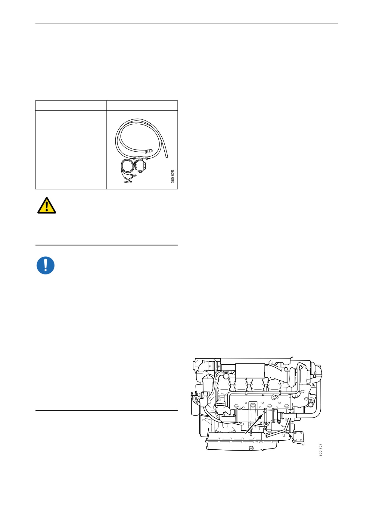
Filling coolant
This procedure applies when the cooling system
has been drained and needs to be filled with a
large amount of coolant.
Special tools
Number, designation
Illustration
2 443 679, coolant
pump
WARNING!
Use protective gloves as coolant can cause irrita-
tion if it comes in contact with the skin. Hot cool-
ant can also cause scalding.
IMPORTANT!
Mix the coolant as specified in the section head-
ed Coolant.
It is not permissible to top up large amounts of
coolant via the expansion tank. Filling via the ex-
pansion tank leads to air locks in the cooling sys-
tem which can lead to e.g. damage to the coolant
pump shaft seal.
Never fill a large amount of cold coolant in a hot
engine. There is great risk of cracks forming in
the cylinder block and cylinder heads.
Do not start the engine until the correct coolant
level has been obtained. If the engine is started
with an insufficient coolant level, it can damage
the coolant pump shaft seal, which leads to cool-
ant leakage.
Filler nipple in the cylinder block (behind the heat
exchanger).
67
Cooling system
1. Open the expansion tank cap.
2. Connect the coolant pump to the filler nipple
in the cylinder block.
3. Connect the pump's 2 cable terminals to the
battery's negative and positive terminal.
Make sure that the filling starts. If the filling
does not start: Change the position of the ca-
ble terminals.
4. Start the engine and run it at idling for
15 minutes.
IMPORTANT!
It is very important that the engine is idling. En-
gine overspeed could damage the coolant pump
shaft seal, which leads to coolant leakage.
5. Switch off the engine and fill with coolant to
the maximum level through the expansion
tank.
Air pockets may still be left in the cooling
system. These will disappear after the engine
has been operated for a period of time.
Therefore, the coolant may need topping up
at a later stage.
Finishing operations
1. Open the bottom valve on the sea water inlet.
2. Start the engine and check that no leakage
occurs.
3. Check the coolant level and top up the cool-
ant via the expansion tank if necessary.
68
Fuel system
Fuel system
Cleanliness requirements
IMPORTANT!
The whole fuel system is very sensitive to dirt
and even very small particles. Foreign particles
in the system can cause serious malfunctions. It
is therefore very important that everything is as
clean as possible when work is carried out on the
fuel system. Before repair work, the engine must
be washed. If possible, a hot water wash should
be used.
It is strictly forbidden to carry out any machining
work or work with compressed air near an open
fuel system.
Be extra careful and always use clean, lint-free
and dust-free clothes and disposable gloves
when working on the fuel system. Scania recom-
mends using Tegera 848 gloves.
Clean tools before they are used and do not use
any worn or chrome-plated tools. Material and
flakes of chrome may come off.
Clean connections and the surrounding area be-
fore removal. When cleaning, cloths or paper
which shed fibres must not be used. Use clean
and lint free cloths, part number 588 879.
Plug or cover the connections during removal.
Also clean the connections before the compo-
nents are fitted. Place removed components on a
thoroughly cleaned, dust-free surface. Scania
recommends using a stainless steel bench top,
part number 2 403 296. Cover the components
with a lint free cloth.
69
Fuel system
Checking the fuel level
Check the fuel level and top up with fuel as nec-
essary.
Note:
If the fuel tank has been run dry or if the engine
has not been used for a long time, bleed the fuel
system. See the section Bleeding the fuel system.
70
Fuel system
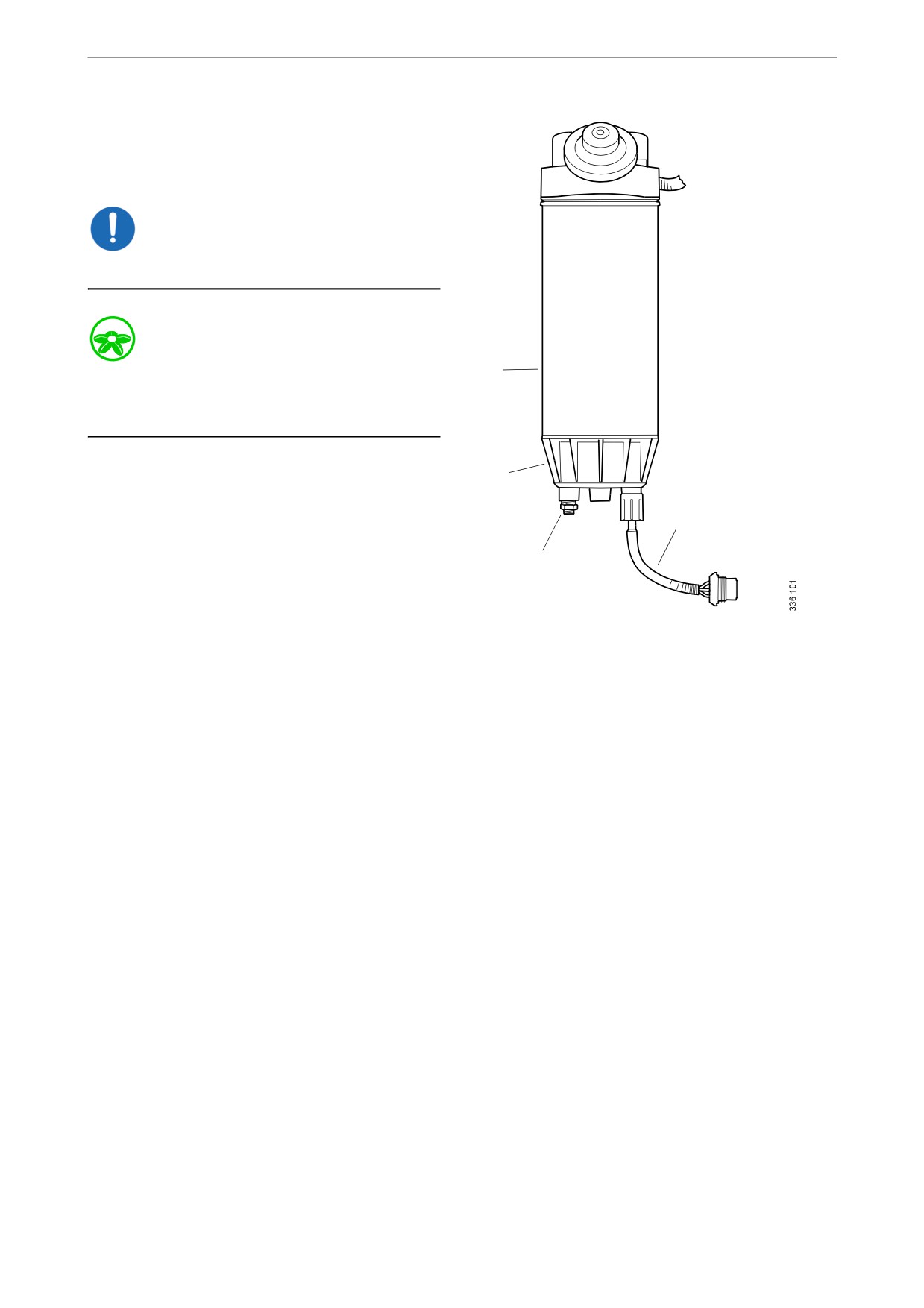
Draining and renewing the
single water separating prefil-
ter (option)
IMPORTANT!
The sensor cable is sensitive. Handle it carefully.
Environment
4
Use a suitable container. The fuel collected must
be disposed of as specified in national and inter-
national laws and regulations.
Before starting work: Close the shut-off cock in
3
the fuel pipe and position a container under the
filter.
1
1. Undo the sensor cable from the connector on
the filter bracket.
2
2. Open the drain tap in the filter cover and let
the fluid run down into the container.
3. Unscrew the filter cover.
1.
Sensor cable.
4. Unscrew the filter from the filter head.
2.
Drain tap.
5. Discard the old filter and use a new filter.
3.
Filter cover.
6. Lubricate the O-ring in the filter cover with
4.
Filter.
engine oil.
7. Screw the filter cover onto the new filter by
hand. Make sure that the drain tap is fully
closed.
8. Lubricate the O-ring on the filter with engine
oil.
9. Fill the width of the filter with clean fuel.
10. Screw the filter into position until the O-ring
rests against the filter head. Tighten the filter
another 1/2 to 3/4 turn by hand.
11. Open the shut-off cock in the fuel pipe and
check that the fuel system is sealed.
12. Screw the sensor cable in the contact housing
onto the filter bracket.
13. Bleed the fuel system according to the in-
structions in the Bleeding the fuel system
section.
71
Fuel system
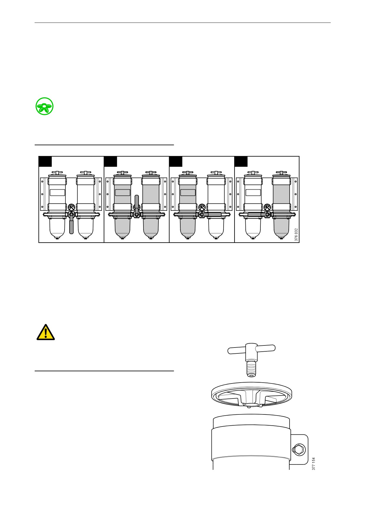
Draining the commutative wa-
ter separating prefilter (op-
tion)
During operation, the arrow on the rotary control
should point towards the filter being used.
Environment
Use a suitable container. The fuel collected must
be disposed of as specified in national and inter-
national laws and regulations.
1
2
3
4
1. Closed; neither filter is active.
2. Both filters are active.
3. Left-hand filter is active.
4. Right-hand filter is active.
1. Switch off the filter that needs renewing. The
arrow on the rotary control points towards
the filter in operation.
WARNING!
Be careful that the valve does not pass the closed
position when the engine is in operation. A
closed position can result in the engine stopping.
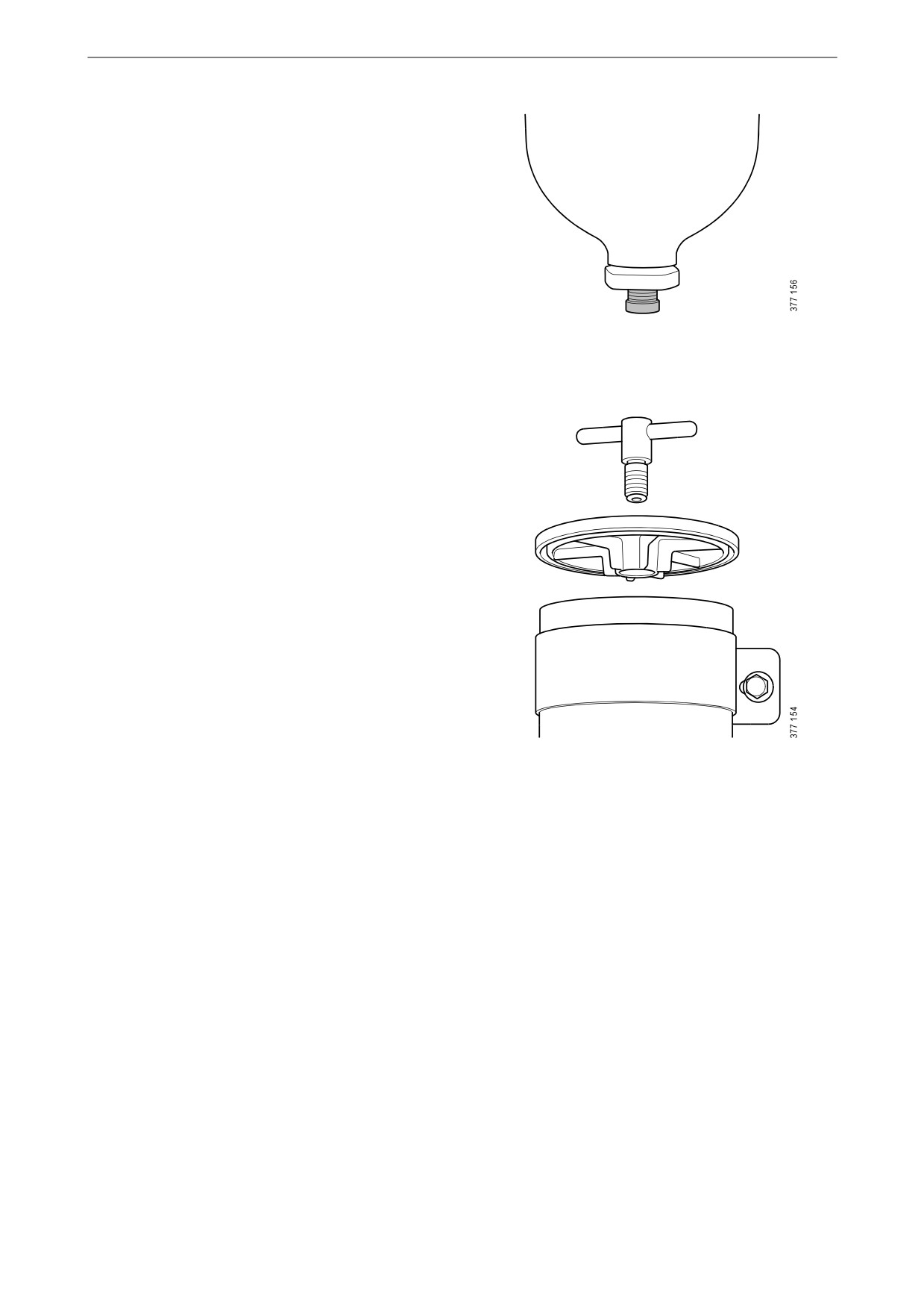
2. Remove the cover from the filter housing.
72
Fuel system
3. Undo the drain plug.
4. Tighten the drain plug when all the water has
emptied.
5. Fill the filter housing with clean fuel.
6. Fit the cover. Tighten the cover screw by
hand.
73

Fuel system
Renewing the commutative
water separating prefilter (op-
tion)
During operation, the arrow on the rotary control
should point towards the filter being used.
Environment
Use a suitable container. The fuel collected must
be disposed of as specified in national and inter-
national laws and regulations.
1. Switch off the filter that needs renewing.
During renewal, the arrow on the rotary con-
trol points towards the filter in operation.
WARNING!
Be careful that the valve does not pass the closed
position when the engine is in operation. A
closed position can result in the engine stopping.
2. Clean the filter housing externally with a
cloth.
3. Remove the cover from the filter housing.
74

Fuel system
4. Remove the filter and fit the new filter.
5. Renew the O-rings in the cover.
6. Lubricate the O-rings with engine oil.
7. Fill the filter housing with clean fuel.
8. Fit the cover. Tighten the cover screw by
hand.
75
Fuel system
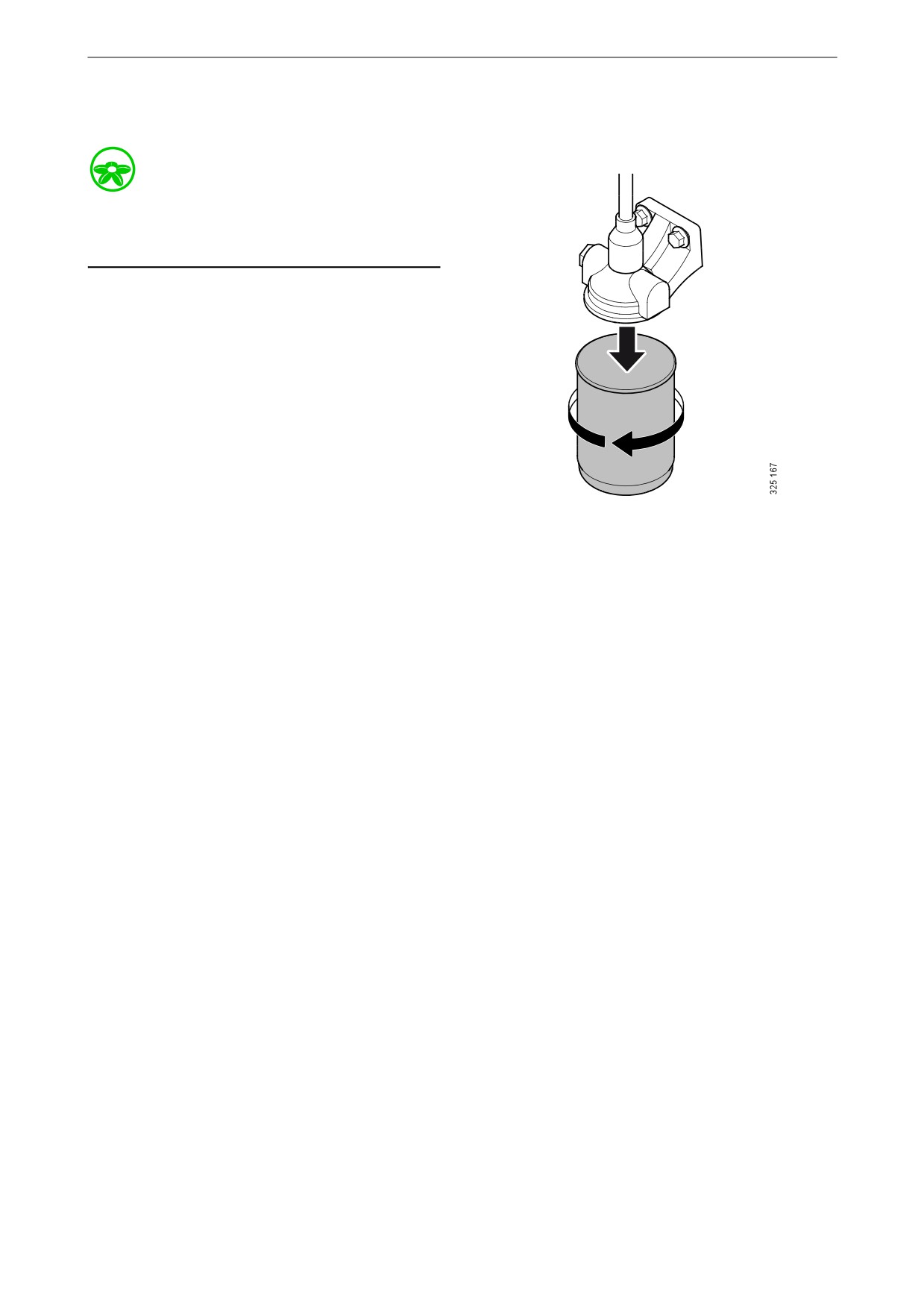
Renewing the fuel filter
Environment
Use a suitable container. The fuel collected must
be disposed of as specified in national and inter-
national laws and regulations.
1. Clean the exterior of the filter with a damp
cloth.
2. Unscrew the filter.
3. Apply oil to the gasket on the new filter.
4. Screw the filter into place by hand until it
makes contact.
5. Screw a further half turn by hand.
6. Bleed the fuel system according to the in-
structions in the Bleeding the fuel system
section.
76
Fuel system
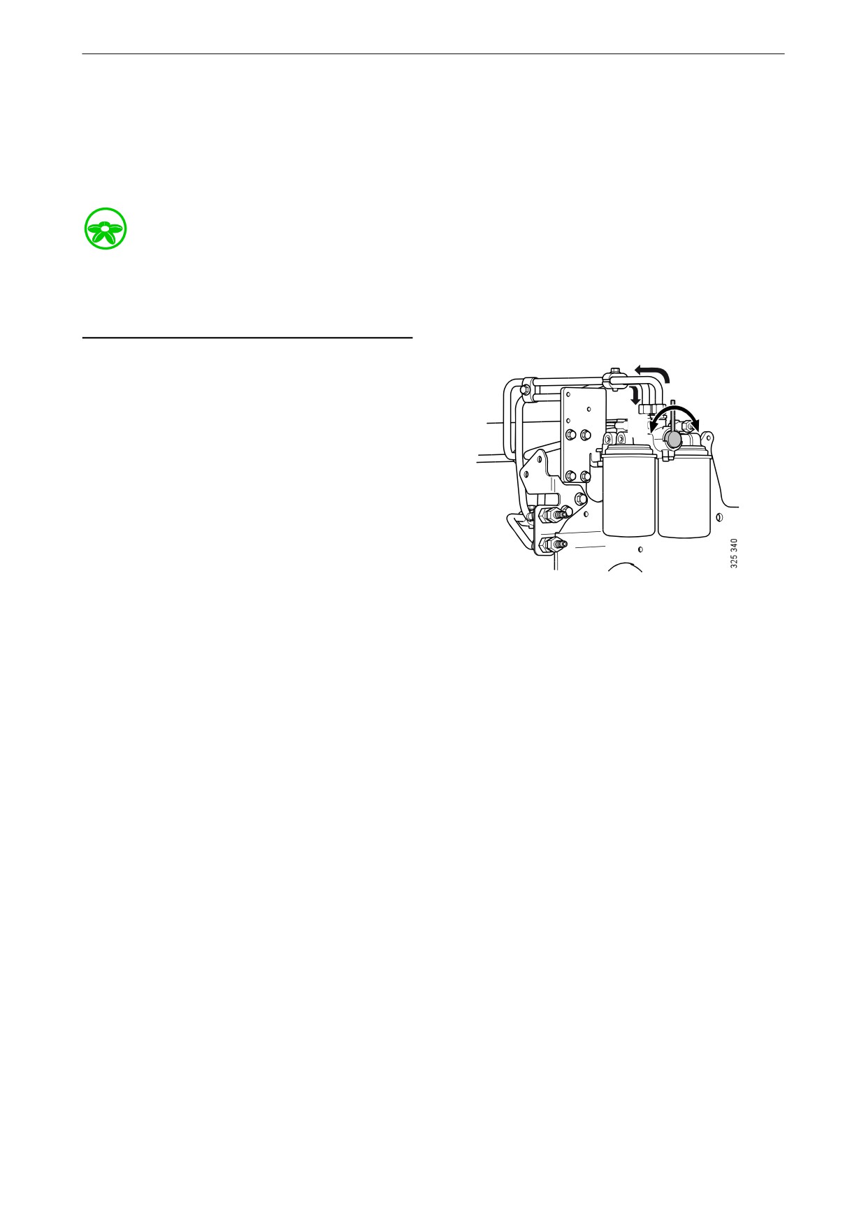
Renewing and bleeding com-
mutative fuel filters (option)
During operation, the rotary control should point
90° towards the filter being used.
Environment
Since the engine may be running during filter re-
newal, fuel spillages may occur. Use a suitable
container. Any fuel collected must be disposed
of as specified in national and international law.
1. Turn the rotary control 90° to the right so that
it points towards filter B. The fuel then flows
through the filter.
B
A
2. Connect a clear plastic hose to the bleed nip-
ple positioned above filter A. Start by wiping
off the bleed nipple. Place the other end in a
A
B
container with a capacity of at least 3 litres
(1 US gallon).
3. Open the bleed nipple on side A. The re-
maining pressure is released.
4. Clean the exterior of the filter with a cloth.
5. Unscrew the filter.
6. Apply oil to the gasket on the new filter.
7. Screw the fuel filter into place by hand until
it makes contact. Turn screw a further half
turn by hand.
8. Turn the rotary control 90° to the left so that
the rotary control points straight up. Both fil-
ters now run simultaneously.
9. When fuel without air bubbles comes out:
Close the bleed nipple. Because the engine is
running, a lot of fuel will come through the
hose.
10. Turn the rotary control 90° to the left so that
the rotary control points towards filter A. Fil-
ter B can now be renewed in the same way as
filter A.
77

Fuel system
Bleeding the fuel system
Bleeding the fuel system using a suc-
tion tool
Tools
Designation
Illustration
Suction tool for fuel sys-
tem
Note:
Scania recommends bleeding the fuel system us-
ing suction tools rather than with a hand pump.
This is a quicker and simpler method, which en-
sures a complete bleeding.
Environment
Use a suitable container. The fuel collected must
be disposed of as specified in national and inter-
national laws and regulations.
1. Attach a clear plastic hose to the bleed nipple
on the fuel manifold. Start by wiping off the
bleed nipple. Place the end of the plastic hose
in a container that holds at least 3 litres (1 US
gallon).
2. Connect the suction tool.
3. Connect compressed air to the suction tool.
Turn the rotary control to create a vacuum.
4. Open the bleed nipple.
5. Hold the suction tool straight and draw out
the fuel. Once the fuel coming out of the
plastic hose is free of air bubbles, then bleed-
ing is complete.
Fuel manifold bleed nipple.
6. Close the bleed nipple. Remove the plastic
hose and suction tool.
7. Start the engine and check that no leakage
occurs.
78

Fuel system
Bleeding the fuel system using a
hand pump
Environment
Use a suitable container. The fuel collected must
be disposed of as specified in national and inter-
national laws and regulations.
1. Attach a clear plastic hose to the bleed nipple
on the fuel manifold. Start by wiping off the
bleed nipple. Place the end of the plastic hose
in a container that holds at least 3 litres (1 US
gallon).
Fuel manifold bleed nipple.
2. Open the bleed nipple and pump with the
hand pump until fuel comes out of the hose.
If the fuel system is empty, it is necessary to
pump approximately 200 strokes in order to
draw up the fuel. Depending on the installa-
tion, a significantly greater number of pump
strokes may be required before fuel comes
out.
3. Pump until fuel without air bubbles comes
out, approximately 20 strokes.
4. Close the bleed nipple and remove the plastic
hose.
Hand pump.
5. Pump approximately 20 strokes with the
hand pump until the overflow valve opens. A
hissing sound should be heard.
6. Start the engine. The engine should be easy
to start.
7. If the fuel filter has been renewed, check that
no fuel is leaking from the filter. If there is
leakage, tighten the filter more.
79