Scania Marine engine. DI13 XPI. Operator’s manual - part 6
Other
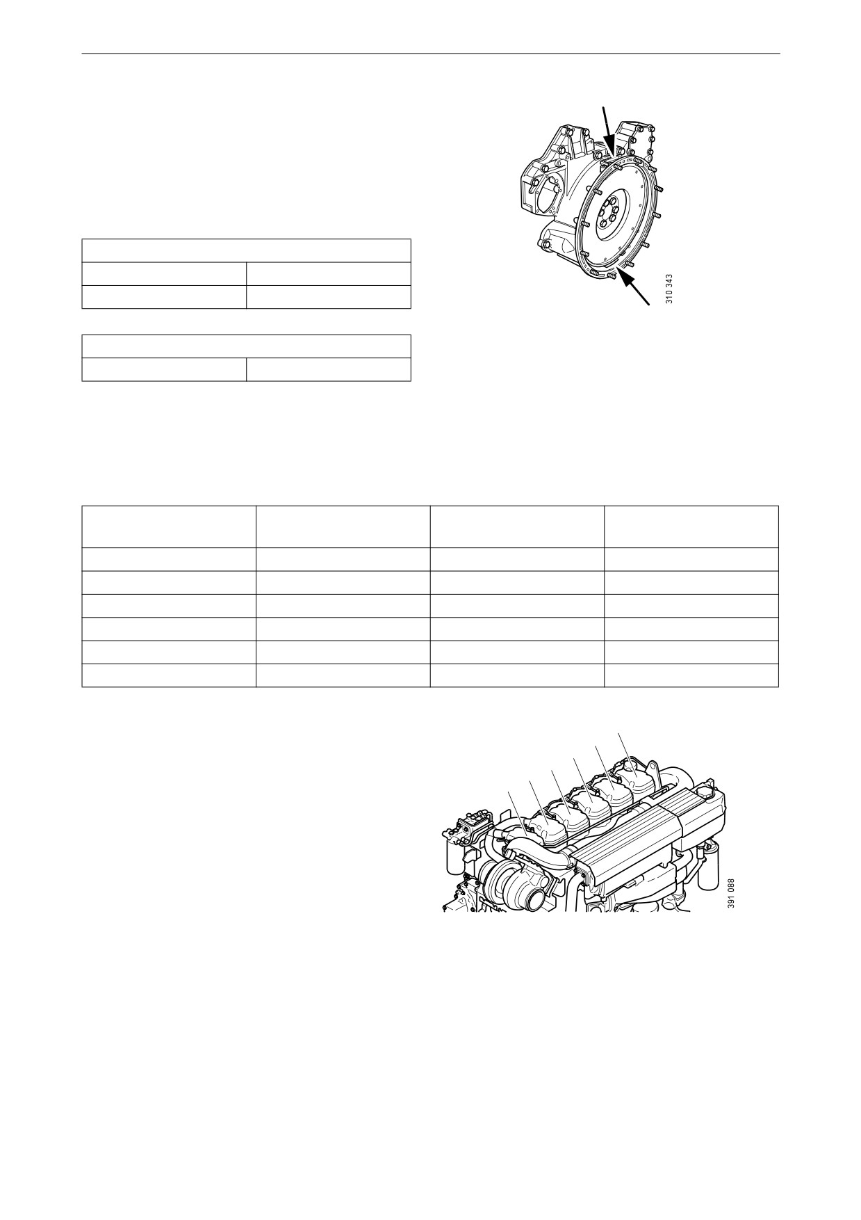
On the flywheel is engraved the reference infor-
mation UP TDC, DOWN TDC and the angle in-
dications listed in the table below. Depending on
the engine installation, this information is visible
in one of the windows, either furthest up or fur-
thest down on the flywheel. See illustration.
Valve clearance, specifications
Intake valve
0.45 mm (0.018 in)
Exhaust valve
0.70 mm (0.028 in)
Upper and lower window to read the engraving on
Tightening torque
the flywheel.
Lock nut for valves
35 Nm (26 lb-ft)
Adjust valves according to the table below. Fol-
low the respective column depending on whether
you are reading the engraving on the flywheel in
the lower or the upper window. Start adjustment
at the top of the table.
Reading in the lower
Valve transition on cyl-
Adjust valves on cylin-
Reading in the upper
window
inder
der
window
DOWN TDC
6
1
UP TDC
120/480
2
5
300/660
240/600
4
3
60/420
DOWN TDC
1
6
UP TDC
120/480
5
2
300/600
240/600
3
4
60/420
1
2
3
4
5
6
Order of cylinders.
80
Other
1. Clean the rocker covers and the area around
them.
2. Remove the rocker covers.
3. Use the turning tool appropriate to the instal-
lation of the engine. Tool 99 309 (or equiva-
lent from other suppliers) is used to rotate the
flywheel from the underside of the engine
and tool 2 402 509 (or equivalent from other
suppliers) is used from the top side.
4. Start adjusting one cylinder according to the
table. Rotate the flywheel until the correct
engraving can be read on the flywheel. It
may be necessary to rotate it more than 1 rev-
olution.
Rotate the flywheel in the rotational direc-
tion of the engine, which is clockwise
viewed from the front of the engine and anti-
3
clockwise viewed from the back of the en-
gine.
During a valve transition, the exhaust valve
(the long arm) is closing at the same time as
4
the intake valve is opening.
The UP TDC engraving on the flywheel is
now visible in the window furthest up on the
flywheel. The DOWN TDC engraving is vis-
5
ible in the lower window.
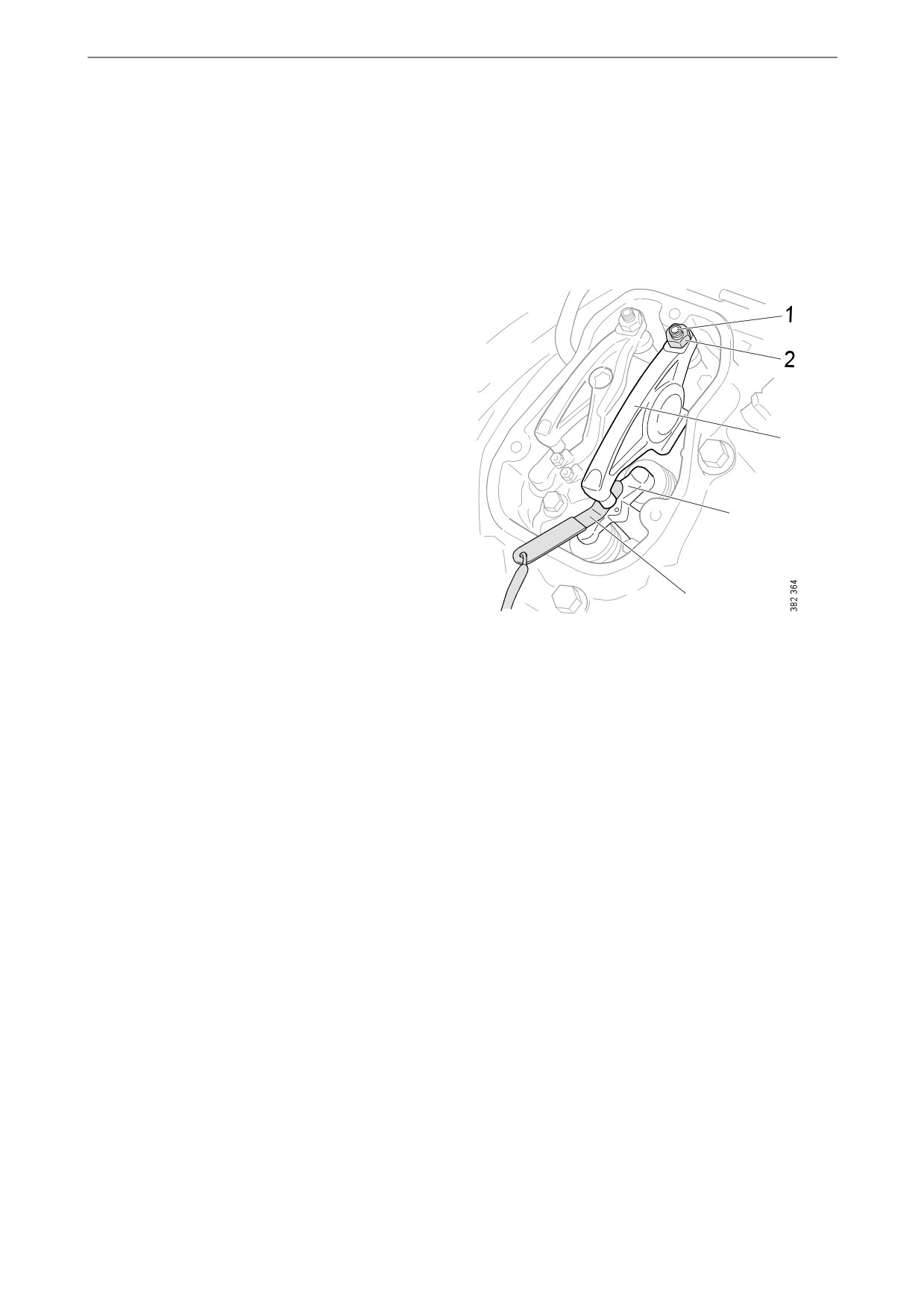
1.
Adjusting screw.
5. Read the table on the previous page to see
2.
Lock nut.
which valve to adjust.
3.
Rocker arm.
6. Stick the feeler gauge under the pressure pad
4.
Valve bridge.
of the rocker arm and check the valve clear-
5.
Feeler gauge.
ance.
7. If necessary, adjust the valve clearance by
a) loosening the lock nut on the end of the
rocker arm
b) adjusting the valve clearance with the ad-
justing screw
c) tightening the lock nut.
8. Mark the rocker arm with the felt-tip pen and
then continue with the next cylinder accord-
ing to the table.
81

Quality requirements for fuel
Sulphur content
Quality requirements for
fuel
IMPORTANT!
Quality requirements and testing standards for
the most important properties of different types
The operator is responsible for using the correct
of fuel are described in the Workshop Manual.
type of diesel to ensure that local laws are com-
This can be ordered from Scania dealers or di-
plied with.
rectly from Scania.
Sulphur content
Note
Diesel
0-2,000 ppm
Normal oil change interval of
up to 500 hours.
(< 0.2%)
Properties
2,000-4,000 ppm
The oil change interval must
The quality of the diesel is very important for the
be halved to a maximum of
(0.2-0.4%)
operation and service life of the engine and the
250 hours.
fuel system, and also for the engine performance.
4,000 ppm
Max. permitted sulphur con-
Note:
tent. If diesel with too high a
(0.4%)
The diesel should comply with the requirements
sulphur content is used, this
of European standard EN590.
causes engine damage.
However, Scania accepts larger tolerances of
Temperature dependence of diesel
certain properties. Please see the table below.
IMPORTANT!
Mixing kerosene or other paraffins with the die-
Property
Requirements
sel is prohibited. The injectors may be damaged.
Viscosity at 40°C
1.4-4.5 cSt
(104°F)
It is not permissible to mix petrol with diesel. In
the long term petrol can cause wear in the injec-
Density at 15°C (59°F)
0.79-0.87 kg/dm3
tors and engine.
Ignitability (CET rating)
minimum 49
Lowest flashpoint
56°C (132°F)
At temperatures lower than those specified for
Particulate contamina-
Classification 22/20/17
the diesel, paraffin wax may precipitate from the
tion level
according to ISO 4406
diesel and block filters and pipes. The engine can
then lose power or stop.
The diesel is adapted for use in the specific cli-
mate of each country. If an engine is to be oper-
ated in a temperature zone with a temperature
lower than normal, first identify the temperature
properties of that particular diesel.
82
Quality requirements for fuel
HVO
Storage of biodiesel
HVO is a synthetic diesel which is manufactured
through the hydrogenation of plants and animal
IMPORTANT!
fats. To the user, HVO is reminiscent of diesel in
accordance with EN590, apart from HVO having
Biodiesel must not be stored for more than 6
a somewhat lower density.
months.
Scania approves the use of up to 100% HVO for
all engines in accordance with the European
Biodiesel has a maximum storage life of
standard EN 15940.
6 months from the date of production to the ex-
piry date. The fuel is affected by light, tempera-
ture, water, etc. during storage, which affects the
fuel characteristics and durability.
Biodiesel also has lower stability against oxida-
Biodiesel (FAME)
tion than diesel. This can result in a thickening of
the fuel and blocking of parts of the fuel system,
Use of biodiesel
e.g. the fuel filter. Bacterial growth can occur
when fuel is stored in tanks under unfavourable
Scania uses the term biodiesel to refer to a re-
conditions. Avoid storage in barrels or auxiliary
newable diesel made from greases or oils and
tanks, except when fuel turnover rates are high.
methanol. The biodiesel should conform to the
Check tank cleanliness whenever refuelling
requirements of European standard EN 14214 or
takes place.
Brazilian standard ANP-45. For biodiesel in ac-
cordance with EN 14214 or ANP-45, the generic
If the engine has been refuelled with biodiesel,
term FAME is frequently used.
and is stationary for a long period, condensation
water can form in the fuel tank resulting in bac-
Normal diesel in accordance with EN 590 can
terial growth.
contain up to 7% biodiesel from the diesel sup-
plier. There are grades of diesel that comply with
See also the section Preservative fuel.
EN 590 but contain a higher mixture of biodies-
el.
Scania approves a mixture of up to 10% biodies-
el.
83
Preparing the engine for storage
Preservative coolant
Preparing the engine for
Use coolant containing 50% by volume of gly-
storage
col. Example: BASF MPG Glysacorr P113 or
If the engine is not being used for an extended
Valvoline Zerex P113 FP.
period its cooling system, fuel system and com-
bustion chamber and outside must be protected
WARNING!
against rust.
The engine can normally stand idle for up to
Ethylene glycol can be fatal if ingested and can
6 months without needing preparation. For
cause skin irritation and eye damage.
longer periods of than 6 months, however, the
measures in the following sections must be tak-
en. These measures provide protection for ap-
Preservative fuel
proximately 3 years, then the preparing
Preservative fuel must not contain biodiesel.
procedure must be repeated. An alternative to
Even small amounts of 5-10% biodiesel can have
preparing the engine for long-term storage is to
adverse effects on the engine when in long-term
start the engine and warm it up every 6 months.
storage.
Preparation means that the following measures
Long-term storage of diesel, where the diesel
are taken:
comes into contact with water, may lead to the
• The engine is cleaned thoroughly.
growth of micro organisms (bacteria and fun-
gus).
• Run the engine for a specific period using
special preservative fuel, oil and coolant.
In order to minimise the growth of micro-organ-
• Otherwise prepare the engine for storage (fil-
isms, preservative fuel should contain the fol-
ter renewal, lubrication, etc.).
lowing additives. The additives should be
selected and added by the fuel supplier.
Preservative products
Preservative fuel should comply with the follow-
ing requirements:
Preservative oil
•
0% biodiesel.
Use a normal engine oil that meets the require-
•
Max. sulphur content 50 ppm.
ments in the Oil grade section.
•
Max. water content 200 ppm.
•
The fuel must contain additives to stop the
growth of micro-organisms.
84
Preparing the engine for storage
Preparations for storage
9. Detach the fuel pipe at the overflow valve
and connect a return hose to a separate can.
10. Connect and bleed the fuel system.
Environment
11. Start the engine and run it at about 1,100 rpm
for 20 minutes.
Use a suitable container. Used oil and coolant
must be disposed of as specified in national and
12. Remove the rocker covers and lubricate the
international laws and regulations.
valve mechanisms with pushrods and the
valve tappets, as well as the injector mecha-
nism, using a liberal amount of preservative
Note:
oil. Refit the rocker covers.
Do not remove the injectors.
13. Drain the coolant if the engine is not to be
stored with coolant in the system. Plug and
tape all coolant connections if the engine is
1. Remove plugs and tape from the coolant
to be stored without coolant in the cooling
connections, air intake and exhaust pipe.
system.
2. Drain the oil.
14. Remove the sea water pump impeller if the
3. Renew the oil filter and fuel filter.
engine has a sea water pump.
4. Clean the centrifugal oil cleaner.
15. Renew or clean the filter element in the air
cleaner.
5. Fill with engine oil to the minimum level on
the oil dipstick.
16. Cover the air intake and exhaust pipe.
6. Drain and flush the cooling system of any old
17. Spray the outside of the alternator and starter
coolant.
motor with water-repellent anti-corrosive
oil: CRC 226, LPS1 or equivalent.
7. Top up with preservative coolant.
18. Spray the outside of bright engine parts, first
8. Mix preservative fuel in a can. Detach the
with penetrating preservative oil such as
fuel pipe at the feed pump suction line and
Dinitrol 25B and then with Dinitrol 112 or
connect a hose from the can.
the equivalent.
19. Clearly mark the engine with the storage
preparation date, and state that the engine
must not be started or cranked.
85
Preparing the engine for storage
Batteries
When the engine is to be taken into
operation again
WARNING!
1. Remove plugs and tape from the coolant
connections, air intake and exhaust pipe.
Wear protective gloves and protective goggles
2. Fill the cooling system with coolant.
when charging and handling batteries. The bat-
3. Fit the sea water pump impeller if the engine
teries contain a highly corrosive acid.
has a sea water pump.
4. Drain the preservative oil.
Remove the batteries and trickle charge them at
5. Renew the oil filter and fuel filter.
the battery charging station. This does not apply
6. Fill with new engine oil.
to batteries specified as maintenance-free by the
manufacturer.
7. Remove the rocker covers and lubricate the
valve mechanisms with pushrods and the
The same applies to short-term storage, even if
valve tappets, as well as the injector mecha-
the engine has not been prepared for storage as
nism, using a liberal amount of oil. Refit the
above.
rocker covers.
8. Drain the preservative fuel from the fuel
Storage
manifold.
After the preparation, the engine should be
9. Connect and bleed the fuel system.
stored indoors in a dry location at room temper-
ature. The engine must be packed in packaging
10. Wash off any preservative oil on the outside
made of VCI plastic to protect against dust, dirt
using white spirit.
and moisture.
86

Technical data
Technical data
General data
Number of cylinders and configuration
6, straight
Working principle
4-stroke engine
Cylinder diameter (mm/in)
130/5.12
Piston stroke (mm/in)
160/6.3
12.7/775.0
Displacement (dm3/in3)
Firing sequence
1 - 5 - 3 - 6 - 2 - 4
Compression ratio
17.3:1
Engine direction of rotation viewed from rear
Anti-clockwise
Fan direction of rotation viewed from front
Clockwise
Cooling
Coolant
Valve clearances, cold engine
Intake valve (mm/in)
0.45/0.018
Exhaust valve (mm/in)
0.70/0.028
Number of teeth on the flywheel
158
Low idling speed (rpm)
600
Maximum full-load speed (rpm)
2,100/2,300
Fuel
Diesel
Approximate weight, without coolant and oil (kg/lb)
With heat exchanger
1,285/2,833
With keel cooling
1,180/2,601
Lubrication system
Oil volume
See Maintenance
Oil cleaning
Centrifugal oil cleaning
Oil cooler
Coolant cooled, full flow
Oil filter
Paper filter, full flow
Interval between oil changes (h)
500
Oil grade
Engines run on low-sulphur fuel
ACEA E5 or E7
Engines not run on low-sulphur fuel
Total Base Number (TBN) > 12
(ASTM D2896)
Oil pressure (bar/psi)
Normal with hot engine and nominal engine speed
3-6/43.5-87
Minimum permitted at idling speed
0.7/10.2
Crankcase pressure (mbar/psi)
-5.4 to 2.0/-0.08 to 0.03
87

Technical data
Intake system
Permissible pressure drop in the intake system with cleaned or new filter
30/0.44
(mbar/psi)
Permissible pressure drop in the intake system with blocked (dirty) filter
65/0.94
(mbar/psi)
Cooling system
Coolant volume (dm3/US gallon)
With heat exchanger
40/10.6
With keel cooling (engine only)
20/5.3
Coolant temperature (°C/°F)
With heat exchanger
90-95/194-203
With keel cooling
83-88/181-190
Number of thermostats
1
Thermostat opening temperature (°C/°F)
With heat exchanger
80/176 and 87/187
With keel cooling
75/167
Fuel system
Injection system
XPI
Control system
EMS
Fuel filter
Scania polymer filter
Fuel filter with water separator
Scania polymer filter
Electrical system
Type
2-pin, 24 V, DC
Starter motor, standard equipment
2-pin, 24 V, 7.0 kW
Alternator, standard equipment
2-pin, 28 V, 100 A
88

Technical data
Material content
The values indicate an approximate percentage
for the different materials that make up the en-
gine.
Material
% by weight
Steel
40
Cast iron (30% recycled)
46
Aluminium
8
Copper, bronze, brass, zinc
1.5
Lead
< 0.1
Plastic
< 1
Rubber
< 1
Glass
0
Paints
< 1
Oils and greases
3
Recycling
Type of material
Recommended recycling method
Metal
Recycling.
Plastic
Recycling, incineration.
Chemicals and oils
Re-use if possible; otherwise hand in to an authorised waste disposal contrac-
tor.
Fuel filter and oil filter
Hand in to an authorised waste disposal contractor.
Colour
No known recycling methods.
Electronics
Hand in to an authorised waste disposal contractor.
89
Scania Assistance
Scania Assistance
Wherever you are, you can always get assistance
from the Scania service organisation, Scania As-
sistance, all day, every day of the year. Always
call the contact for your country.
AR
0800 999 722 642
LU
+32 226 400 000
AT
+43 1 256 44 11
MA
+32 2264 0000
AU
1300 SCANIA
ME
+381 60 8484 122
1300722 642
MW +27 11 2265005
BA
+38761 225 917
MY
1800 08 8500
BE
+32 2 264 00 00
+60355909077
BG
+359 886 660 001
MX
01 800 4SCANIA
BR
0800 019 42 24
NA
+27 11 226 5005
BW
+27 11 226 5005
NL
+31 76 52 54 111
CA
+1-800-2-SCANIA
NO
+47 223 217 00
CH
+41 800 55 24 00
PE
0800 51 727
CL
188 800 722 642
PL
+48 22 331 22 33
CZ
+420 225 020 225
PT
+34 91 678 9237
DE
+49 261 8878888
RO
+40 723 27 27 26
DK
+45 333 27044
RS
+381 60 8484 122
EE
+372 5153 388 (Tallinn)
SE
+46 42 100 100
+372 5126 333 (Tartu)
SG
(65) 6591 7180
+372 5071 477 (Pärnu)
+65 6861 9181
+372 5047 655 (Rakvere)
SI
+386 1 2427 606
ES
+34 91 678 80 58
SK
+421 903 722 048
FI
+358 10 555 24
TR
+90,444 72 44
FR
+33 2 41 41 32 32
TZ
+27 11 226 5005
GB
0 800 800 660
US
1-800-2-SCANIA
+44 1274 301,260
UY
0800 8351
GR
+30 6944 420,410
ZA
0800 005 798
HU
+36 209 727 197
+27 11 226 5005
IE
+353 71 963 4000
ZM
+27 11 2265005
IT
+39 0461 996 222
ZW
+27 11 2265005
KR
+82 1588 6575
Other countries:+46 8 52 24 24 24
Note:
Calls will be recorded for training purposes.
90

General tightening torques for screw joints
General tightening torques
for screw joints
Hexagon screws, hexagon
socket screws, Torx screws,
hexagon nuts
Metric thread. Strength class 8.8/8.
Tightening torque
Thread
Nm
Lb-ft
M4
2.9
21
M5
6
4
M6
9.5
7
M8
24
18
M10
47
35
M12
84
62
M14
135
100
M16
210
155
M18
290
214
M20
420
310
M22
580
428
M24
730
538
Flange screws with hexago-
nal head and hexagonal
flange nuts
Metric thread. Strength class 8.8/8.
Tightening torque
Thread
Nm
Lb-ft
M5
6.7
5
M6
10.2
8
M8
26
19
M10
50
37
M12
92
38
M14
149
110
M16
184
136
91
General tightening torques for screw joints
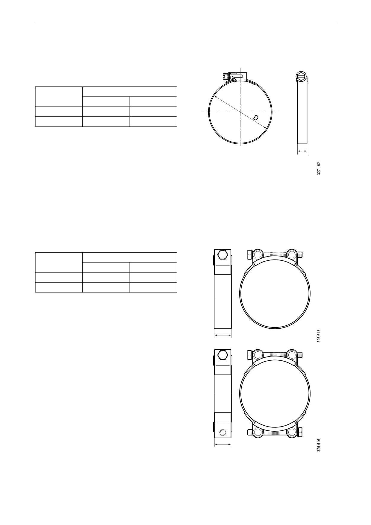
Hose clamps
Specifications in the tables show tightening
torque when tightening by hand.
A = width
Tightening torque
(mm)
Nm
Lb-ft
7.5-9
1.5
1
12
5
4
A
Tightening torque for new unfitted hose clamp is
max 1 Nm (0.7 lb-ft).
A = width
Tightening torque
(mm)
Nm
Lb-ft
20
10
7
25
20
15
A
A
92