Scania DI14 69 (750 hp), DI14 82 (800 hp). Marine engine. Operator’s manual - part 3
8. Every 400 hours:
CHECKING COOLANT
Coolant should be checked as follows:
a) Check the appearance of the coolant.
b) Coolant with glycol: Check the glycol content.
c) Coolant with Scania Anti-corrosive:
Coolant composition:
Check the corrosion protection.
If there is a danger of freezing:
The composition of the coolant is also described under
at least 30% glycol by volume
“Starting and running”.
max. 50% glycol by volume
a)
If there is no danger of
Checking the appearance of the coolant
freezing:
- Take a little coolant in a vessel and check that it is clean and clear.
7-12% by volume
- If the coolant is contaminated or cloudy: Consider changing the coolant
Scania Anti-corrosive
- The water for the coolant should be free of dirt.
- Use drinking water with a pH of 6 - 9.
b)
Checking glycol content
If there is a danger of freezing, use only glycol as protection against corrosion
Ethylene glycol is highly
in the coolant.
dangerous if ingested and can
- Cooling systems with glycol must contain at least 30% glycol by vol-
prove fatal.
ume to offer sufficient protection against corrosion.
Avoid skin contact with glycol.
-
30% glycol by volume provides anti-freeze protection down to -16 °C.
If more protection is required, see the table on the next page for calculat-
ing the necessary amount of glycol.
We recommend only nitrite-free glycol anti-freeze with the following sup-
plier designations:
The coolant should be ready
BASF G48 or BASF D542
mixed when it is poured into the
- Top up with glycol if the glycol content is less than 30% by volume. A
cooling system.
glycol content greater than 50% by volume will not provide more anti-
Never top up with only water or
freeze protection.
only glycol.
- The table shows the temperature at which ice (slush) starts to form. The
engine freezes and breaks at significantly lower temperatures, see graph.
- Ice forming in the coolant often causes malfunction without any risk of
damage. The engine must not be loaded hard when ice is forming.
Note: The coolant should be changed when the cooling system is
The recommended glycol must
cleaned: every 1,200 hours or at least every 3rd year.
not be mixed with glycol having
nitrite-based anti-corrosive.
Important: If a coolant filter is used in the cooling system, it must not
Risk for build up of sludge and
contain an inhibitor.
reduced cooling capacity.
32
2001-05:1

% glycol by volume
Properties of glycol at low temperatures:
- Example with 30% glycol by volume
- Ice slush starts to form at -16°C.
- There is risk for malfunctions at -30°C
No risk of damage by freezing with a minimum
content of 30% glycol by volume
Curve A: Ice build up starts (slush)
Curve B: Temperature at which damage due to
freezing can occur
1. Safe range
2. Malfunctions may occur (ice slush)
3. Risk of damage by freezing
A
% glycol by
15
20
25
30
35
40
45
50
60
Cooling
volume
system
Ice slush starts
capacity, dm3
-6
-9
-12
-16
-22
-27
-36
-46
-55
to form at °C
5
6
8
9
11
12
14
15
18
30
6
8
10
12
14
16
18
20
24
40
8
10
13
15
18
20
23
25
30
50
9
12
15
18
21
24
27
30
36
60
11
14
18
21
25
28
32
35
42
70
12
16
20
24
28
32
36
40
48
80
14
18
23
27
32
36
41
45
54
90
15
20
25
30
35
40
45
50
60
100
Glycol dm3
17
22
28
33
39
44
50
55
66
110
(litres)
18
24
30
36
42
48
54
60
72
120
20
26
33
39
46
52
59
65
78
130
21
28
35
42
49
56
63
70
84
140
23
30
38
45
53
60
68
75
90
150
24
32
40
48
56
64
72
80
96
160
26
34
43
51
60
68
77
85
102
170
27
36
45
54
63
72
81
90
108
180
29
38
48
57
67
76
86
95
114
190
30
40
50
60
70
80
90
100
120
200
A = Range to be avoided. Only for calculation of glycol mix.
Freezing point of coolant when ice slush starts to form at different glycol mixes
2001-05:1
33

b)
Checking Protection against corrosion
There must always be sufficient anti-corrosive (inhibitor) in the coolant to
Corrosion inhibitor, if
protect the cooling system against corrosion.
swallowed can be fatal.
If there is no danger of freezing use only Scania Anti-corrosive.
Avoid contact with the skin.
The inhibitor in Scania Anti-corrosive is nitrite-free.
The correct level of anti-corrosive is 7-12% by volume.
- Fill with Scania Anti-corrosive as indicated on the packaging.
- Topping up with 1.0% by volume of Scania Anti-corrosive should be
Mixing corrosion inhibitor with
done after every 400 operating hours.
glycol or adding too much
- Never top up with water only or anti-corrosive only. Lost fluid should
corrosion inhibitor may cause
always be replaced with pre-mixed coolant:
deposits and reduced cooling
water + 10% Scania Anti-corrosive by volume.
capacity.
Note: The coolant should be changed when the cooling system is cleaned:
every 1,200 hours or at least every 3rd year.
If a coolant filter has been fitted
it must not contain inhibitor.
Changing the coolant
1. Remove the filler cap from the expansion tank.
2. The coolant is drained at two points:
- the ”lowest point” of the engine block, see drawing
- the ”lowest point” of the cooling system.
3. Close the drain cocks.
4. Fill coolant through the expansion tank filler hole.
Mix coolant as described on page 32.
Always collect fluid in a suitable
container to avoid spillage when
changing coolant.
Dispose of used coolant through
an authorized waste disposal
contractor.
34
2001-05:1

9. Every 1200 hours:
CLEANING THE COOLING SYSTEM
Note: If necessary, the cooling system should be cleaned more often.
External cleaning
The cooling system must never
Heat exchanger
be cleaned with caustic soda.
1. Drain the coolant from the engine, see “Changing coolant”.
There is a risk of damage to
aluminium parts.
2. Close the bottom valve or valves and drain the seawater circuit.
3. Disconnect the heat exchanger’s seawater pipe connections and the con-
nections to the charge air coolers, oil cooler and block.
4. Remove the heat exchanger assembly and dismantle it as illustrated.
5. Clean the outside of the element. Use a paraffin-based engine cleaner.
There are springs and retainers
6. Remove any deposit on the inside of the pipes using a round file.
in the heat exchanger, between
7. Assemble the heat exchanger. Change damaged and hardened O-rings.
the housing and the element,
which are not illustrated.
8. Make sure that the thermostats are in place and fit the heat exchanger
back in place on the engine. Reconnect the pipes to the charge air cool-
ers and oil cooler and also the return line from the block.
9. Fill the system with coolant as described in the specifications on
page 32.
1. Housing
15. Gasket
2. Spiral pin
16. O-ring
3. Element
17. Bolt
4. O-ring
18. Gasket
5. Gasket
19. Flange pipe
6. Gasket
20. Gasket
7. Cover
21. Bolt
8. Bolt
22. Bolt
9. Washer
23. Plug
10. Cover
24. Washer
11. Bolt
25. Washer
12. O-ring
26. Bolt
13. Plug
27. Bolt
14. Sacrificial anode
2001-05:1
35
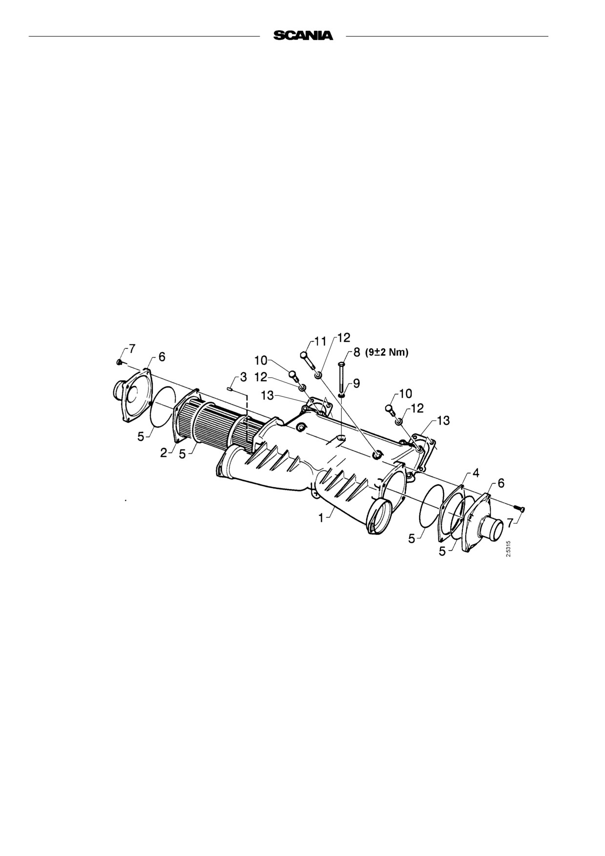
Seawater-cooled charge air cooler
1. Disconnect the connecting pipes for air and seawater and remove the
charge air cooler assembly.
2. Dismantle the charge air cooler as illustrated.
3. Clean the outside of the element. Use a paraffin-based engine cleaner.
4. Remove any deposit on the inside of the pipes using a round file.
5. Assembly the charge air cooler. Change any damaged and hard O-rings.
6. Refit the charge air cooler assembly after the seawater-cooled charge air
coolers have been cleaned and assembled.
Tighten bolt 8 to 9±2 Nm.
Note: On assembly, silicone (816 064) should be applied to both sides of
new gaskets 13.
7. Refit the pipe connections for air and seawater.
1. Housing
8. Bolt
2. Element
9. Washer
3. Spiral pin
10. Bolt
4. Spacer
11. Bolt
5. O-ring
12. Washer
6. Cover
13. Gasket (2)
7. Bolt
36
2001-05:1
Coolant-cooled charge air cooler
1. Drain the coolant from the engine, see “Changing the coolant”, and
drain the seawater circuit if this has not been done when cleaning the
heat exchanger.
2. Remove the catwalk, delivery pipes, fuel filter and water pipes to the
turbo unit.
3. Remove the rear, transverse charge air cooler (seawater-cooled).
4. Undo the charge air cooler’s inlet and outlet pipe connections.
5. Dismantle the charge air cooler as illustrated.
The cooling system must never
Exercise care - do not damage the element’s water connections.
be cleaned with caustic soda.
6. Clean the outside of the element. Use a paraffin-based engine cleaner.
There is a risk of damage to
7. Clean and degrease the sealing surfaces on the core and the air intake
aluminium parts.
manifold upper and lower parts with a spirit based cleaner.
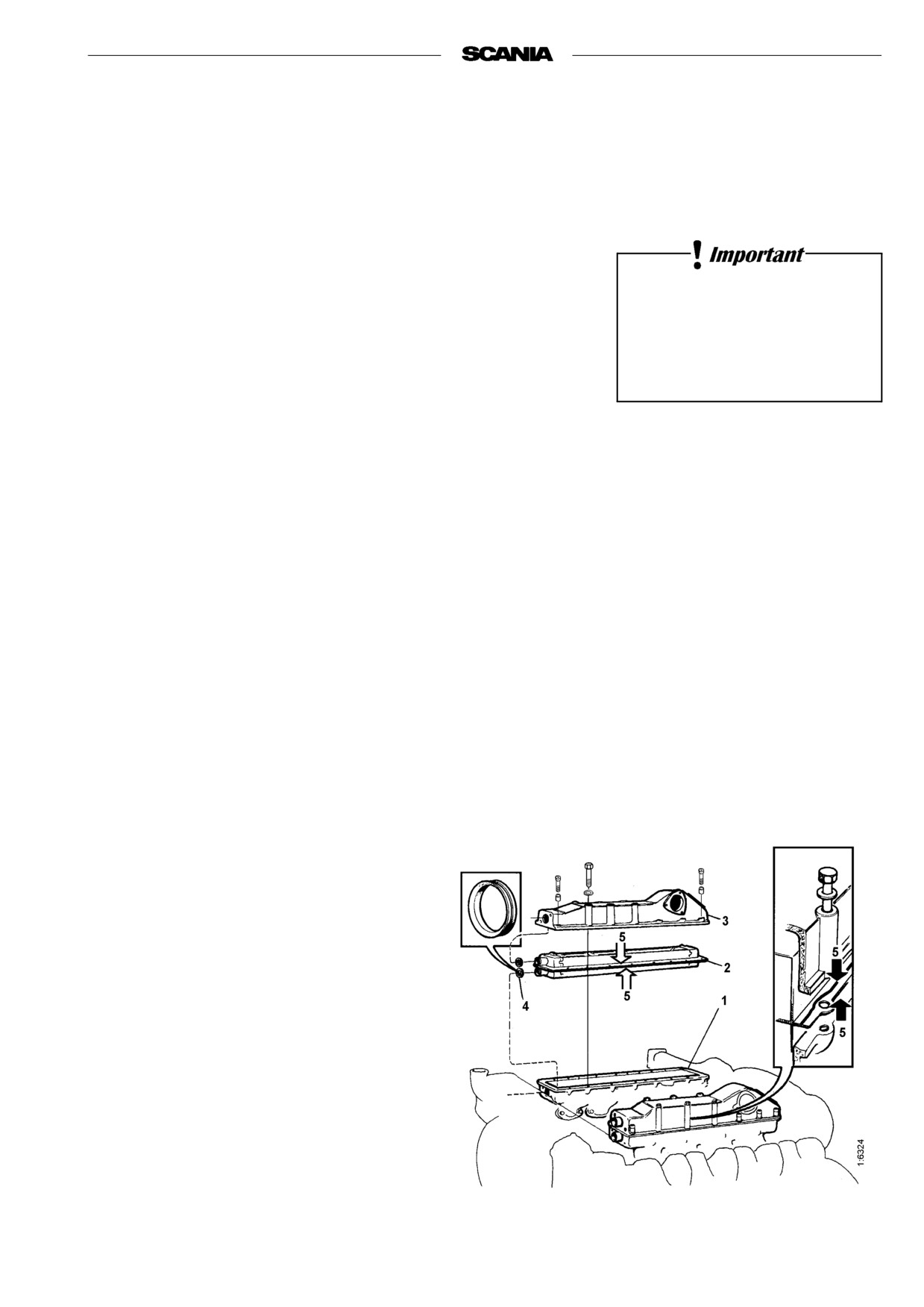
8. Apply sealant (silicone 816 064) in a uniform bead, approximately
2-3 mm, on both sealing surfaces of the element.
9. Fit new V-ring seals on the connections of the element.
10. Assemble the charge air cooler within 15 minutes of applying the sea-
lant. Torque tighten the bolts to 50 Nm.
11. Reconnect the inlet and outlet pipe connections and refit the delivery
pipe, fuel filter and other parts that have been removed.
12. Refit the transverse charge air cooler and its pipe connections for air and
seawater.
Note: On reassembly, apply silicone to the sealing surfaces against the
seawater-cooled charge air cooler and its gaskets.
13. Fill up with coolant as per the specifications on page 32.
Important Allow the sealant to cure for minimum
24 hours before the engine is used.
1. Intake manifold,
lower part
2. Radiator element
3. Intake manifold,
upper part
4. V-ring seal
5. Sealant 816 064
2001-05:1
37
Internal cleaning
Removing oils and greases
- If possible, run the engine until it is warm and then drain the cooling
system.
- Remove the thermostats. This will necessitate removal of the heat
exchanger assembly. It is therefore advisable to do this in connection
with cleaning the heat exchanger.
- Fill the system with clean, hot water mixed with liquid dishwasher
Handling cleaning agents for
detergent designed for household machines. Mix 1% (0.1/10 l).
the cooling system:
- Warm up the engine for about 20 or 30 minutes. Do not forget the cab
Read the warning label on the
heating system, if any.
container.
- Drain the cooling system.
- Fill the system again using clean, hot water and run the engine for about
20-30 minutes.
- Drain the water from the system.
- Refit the thermostats.
- Fill the system with coolant as described in the specifications on
page 32.
Always collect fluid in a suitable
Removing deposits
container to avoid spillage when
- If possible, run the engine until it is warm and then drain the cooling
draining coolant.
system.
Dispose of used coolant through
- Remove the thermostats. This will necessitate removal of the heat
an authorized waste disposal
exchanger assembly. It is therefore advisable to do this in connection
contractor.
with cleaning the heat exchanger.
- Fill the system with clean, hot water mixed with one of the commer-
cially available radiator cleaners based on sulphamic acid and contain-
ing dispersing agents. Follow the manufacturer’s instructions for mix
ratios and cleaning times.
- Run the engine for the specified time and then drain the cooling system.
- Fill the system again with hot water and run the engine for about 20 or
30 minutes.
- Drain the water from the system.
- Refit the thermostats.
- Fill the system with coolant as described in the specifications on
page 32.
Preventive replacement of coolant pump gear
Note: To be carried out in connection with cleaning of the cooling
system.
- Remove the coolant pump.
- Remove the drive gear.
- Fit a new gear and tighten the nut to 200 Nm.
Note: Do not apply the tightening torque to the gear itself.
- Refit the coolant pump, using new gaskets for the timing gear cover.
38
2001-05:1
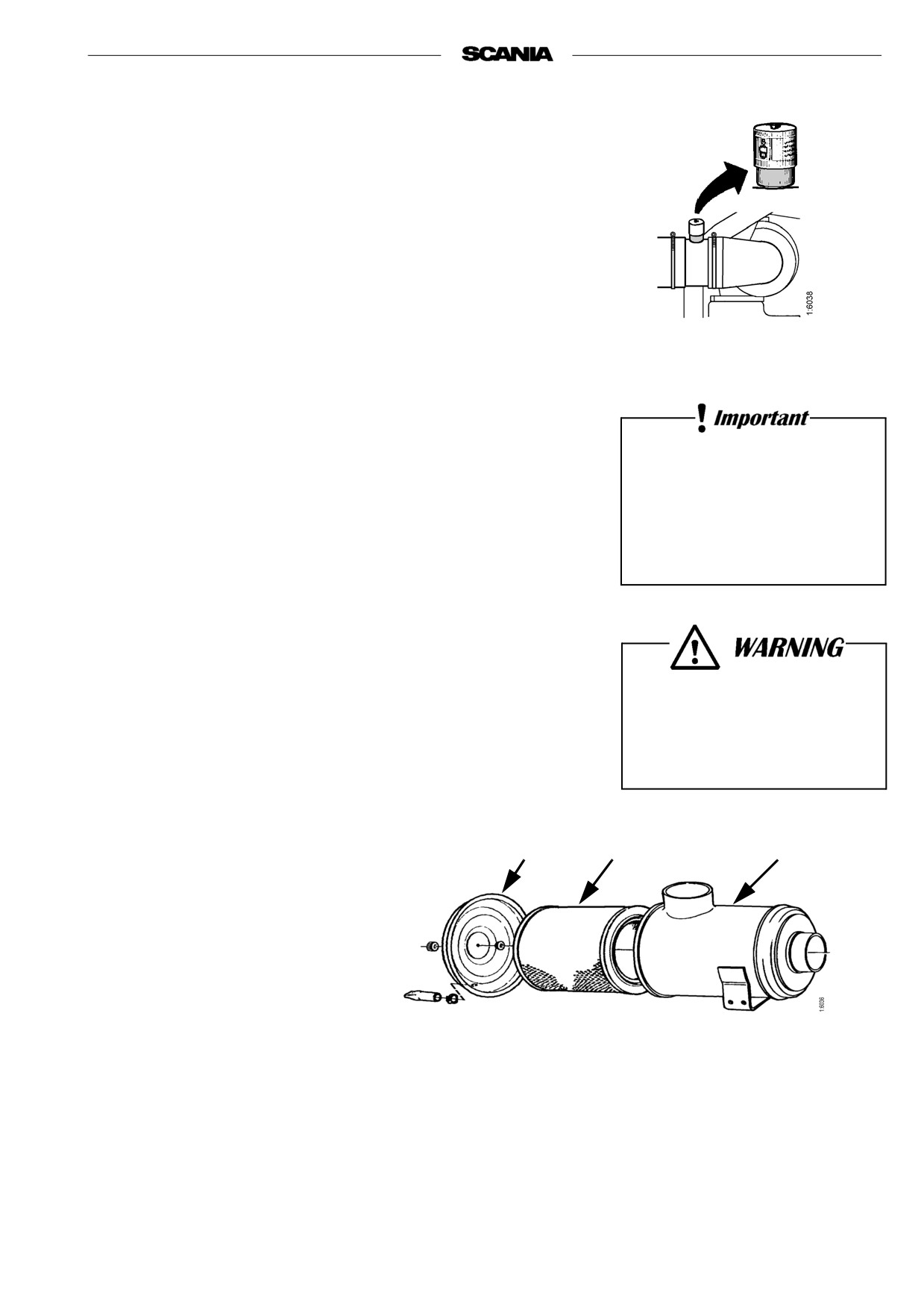
AIR CLEANER
10. Daily:
TEST READING
LOW PRESSURE INDICATOR
If the indicator’s red plunger is fully visible, change or clean the air cleaner
filter insert, point 11.
11. Every 1,200 hours:
Only use Scania genuine air
CLEANING OR CHANGING THE
filter. Change the filter element
FILTER INSERT
if it is damaged.
Note: Earlier if low pressure indicator shows red.
Danger of engine damage if the
Dismantling
filter element is damaged.
1. Remove air cleaner’s side cover.
2. Change or clean the insert.
Note: Cleaning the insert always entails a risk of damage. The insert
may be cleaned no more than four times. After cleaning, it has a
lower dust capacity than a new insert.
Never start the engine unless
3. Mark the filter when it has been cleaned.
the air filter is installed.
Danger of personal injury or
Cleaning insert
engine damage.
- Carefully blow the filter insert clean using dry compressed air from the
inside.
Note: This insert must not be washed using water.
1
2
3
1. Cover
2. Filter insert
3. Filter housing
2001-05:1
39

Checking
- Insert a flashlamp into the insert and check from the outside that there
are no holes or cracks in the filter paper.
- Change the filter insert if there is any damage at all. Danger of engine
damage.
Assembly
1. Assemble the air cleaner in reverse order.
2. Reset the red plunger in the low pressure indicator by pressing in the
button.
Filter with non-replaceable insert (unit cleaner)
Cleaning
- The filter must be cleaned no more than 3 times. Make a mark on it each
time it is cleaned.
- Use a washing solution consisting of water mixed with about 1% mild
detergent.
1. Pour the washing solution into the filter outlet while turning the filter so
that the solution runs out of it opposite to the direction of air flow.
2. Leave the filter in the washing solution for 5 minutes and then lift it to
drain off the solution.
3. Rinse the filter with about 30 litres of clean water at 30 - 40 °C. Pour the
rinse water into the filter in the same way as the washing solution.
4. Lift the filter and allow the rinse water to drain.
5. Repeat this procedure until the rinse water runs clear.
6. Leave the filter to dry in a warm place for a day or so.
Note: The filter must not be blown dry using compressed air.
40
2001-05:1

FUEL SYSTEM
Be extremely careful with
12. Daily:
cleanliness when working on
the fuel system.
CHECKING THE FUEL LEVEL
Malfunctions
- Top up fuel if necessary.
can easily arise and the
- If the tank is run dry, bleed the fuel system, see point 13.
injection equipment
can be damaged.
13. Every 1200 hours:
CHANGING THE FUEL FILTER
Fuel tanks
- Drain any water from the fuel tanks.
Filter
The filter consists of two filter units connected in parallel.
- Wash the outside of the filters and unscrew them. Dispose of the filters
according to environmental regulations.
- Tighten the new filters by hand.
Never use tools. The filters may be damaged, inhibiting circulation.
- Bleed the fuel system as described below.
- Start the engine and check for leaks.
Bleeding the fuel system
- Open bleed screw 1 on the main filter.
Only use Scania genuine fuel
filter.
- Pump hand pump 2 until air-free fuel flows out at the main bleed screw.
- Close the bleed screw. Pump a few times using the hand pump.
If the engine is difficult to start after bleeding
- Slacken injection pump overflow valve 3 half a turn
Always collect fuel in a suitable
and make a fresh attempt to start.
container to avoid spillage when
If the engine still won’t start
bleeding system or renewing
- Pump the hand pump until bubble-free fuel flows from the overflow
components.
valve.
Tighten the overflow valve when the engine has started.
2
3
2001-05:1
41

14. Every 1,200 hours:
1. Socket nut
CHECKING INJECTORS
2. O-ring
Injectors should be inspected by trained personnel with access to the required
3. O-ring
equipment, at least once every year or every 2,400 hours.
4. Stop ring
Removal
5. Guide pin
1. Clean around the injectors and connections including clamps and
6. Seal
brackets.
2. Undo the leak-off pipes and bunch of delivery pipes. Be careful to
avoid bending any of the delivery pipes.
3. Unscrew the injector.
4. Place protective plugs on the injector and delivery pipe.
5. Lift the seal from the bottom of the injector seat if it does not come out
together with the injector.
The delivery pipes must
6. Place a seal plug in the injector seat in the cylinder head.
not be bent.
7. Clean the injectors and check/adjust in an injector tester.
All clamps must be refitted.
Correct opening pressure, see Technical data, page 52.
Fitting
1. Check that there is no old seal in place and fit a new seal in the bottom
of the injector seat.
Always wear gloves and eye
2. Fit a new O-ring in the socket nut and a new seal under it.
protection when testing
3. Fit the injector.
injectors.
4. Tighten the socket nut to 70 Nm (7.0 kgfm).
Fuel escaping under high
5. Fit the delivery pipe and tighten the cap nuts to 20 Nm (2.0 kgfm).
pressure can penetrate body
Fit clamps and brackets.
tissue and cause serious injury.
Take care to fit the delivery pipe without tension and make sure that
the cone on the delivery pipe is correctly positioned in the connection.
6. Fit the leak-off fuel line. Tighten the bolts to 11 Nm (1.1 kgfm).
1. Delivery pipes
2. Cap nut
3. Washer
4. Cone
5. Connection on injector or
injection pump
Delivery pipe connection
42
2001-05:1
ELECTRICAL SYSTEM
15. Every 200 hours:
Do not let open flame or sparks
CHECKING THE ELECTROLYTE
come near the batteries.
LEVEL IN BATTERIES
When batteries are charged,
they emit highly flammable
1. Unscrew the plugs and check the electrolyte level in all cells.
fumes that can explode.
2. Top up with distilled water until the level is 10-15 mm above the plates.
16. Every 200 hours:
CHECKING THE CHARGE STATE
OF THE BATTERIES
- Check the specific gravity using a hydrometer (battery electrolyte
tester).
Wear gloves and eye protection
In a fully charged battery it should be:
when charging and
1.280 at +20 °C
handling batteries.
1.294 at 0°
Batteries contain a highly
corrosive acid.
1.308 at -20 °C
- If the specific gravity is below 1.20, the battery must be charged.
A discharged battery freezes at -5 °C.
- Trickle charging is recommended during the winter if the engine is not
used.
Avoid boost charging. This will damage the battery in the long term.
17. Every 200 hours:
Do not connect the cables to the
wrong terminals.
CLEANING BATTERIES
This could cause serious
1. Clean batteries, cables and cable terminals.
damage to the electrical system.
2. Check that all cable terminals are well tightened.
If the terminals are
shortcircuited, sparks
3. Grease posts and cable terminals using petroleum jelly.
will be generated.
2001-05:1
43
CHANGING BATTERY
Removal
Do not connect the cables to the
1. Detach the negative lead (-) from the battery (cable to engine casing).
wrong terminals.
2. Detach the positive lead (+) from the battery (cable to starter motor).
This could cause serious
Fitting
damage to the electrical system.
If the terminals are short-
1. Connect the positive lead (+) to the battery (cable to starter motor).
circuited, sparks will be
2. Connect the negative lead (-) to the battery (cable to engine casing).
generated.
Dispose of used batteries
through an authorized waste
disposal contractor.
18. Every 400 hours:
CHECKING THE COOLANT LEVEL
MONITOR
(optional equipment)
Note: The level monitor should be checked when the engine is cold.
1. Undo the clamps on the level monitor’s lead to the wiring harness on the
engine and unplug the connector.
2. Place a receptacle under the coolant pump and unscrew the monitor.
Immediately fit a plug with an M18x1.5 thread in the hole for the moni-
tor. Avoid getting the coolant on your skin.
3. Plug in the monitor’s connector and set the control switch to ”ON”.
4. Check that the indicator lamp remains on and that the buzzer sounds.
5. Submerse the monitor in liquid in a metal receptacle (steel). It is impor-
tant to ensure that the body of the monitor is in contact with the metal.
6. The indicator lamp should go out after about 2 seconds.
7. Remove the monitor from the liquid. In about 7 seconds the indicator
lamp should come on and the buzzer start to sound.
8. Unplug the monitor’s connector and screw the monitor back in place.
9. Clamp the monitor’s lead as before and plug in the connector.
10. Fill the system with coolant as described in the specifications on
page 32.
44
2001-05:1

MISCELLANEOUS
19. Every 200 hours:
CHECK/TENSION
V-BELTS
If correctly tensioned, a pressure of 35-50 N on a drive belt
(depending on the free length of the belt) should deflect it
about 10 mm.
Change worn or damaged belts.
1. Detach the securing screws.
2. Set the correct tension using the adjusting screw.
Do not overtighten the belts.
Measurement using a Krikit belt tension gauge
(Part. No. 587 495)
1. Zero the gauge by pressing the measuring arm.
2. Place the gauge on the V-belt at an equal distance from two pulleys.
3. Press until the gauge clicks.
4. Read the gauge.
- The recommended tension of genuine Scania belts
when tested is 300 N.
When changing belts, slightly higher (10-15%) tension should be used.
2001-05:1
45

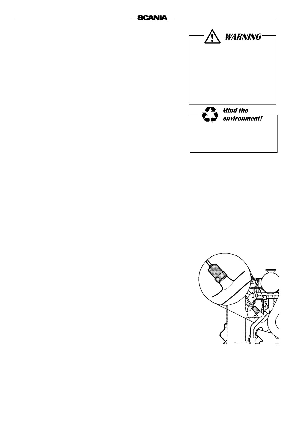
20. Daily:
LOOK FOR LEAKS,
REMEDY AS NECESSARY
- Start the engine.
- Look for leakage of oil, coolant, fuel, air and exhaust.
- Tighten or change leaking connections. Check the overflow holes (1)
Ensure that any leakage does
which show whether the O-rings between the cylinder liner and crank-
case are leaking, see drawing.
not pollute the environment.
a) If coolant is leaking out, the two upper O-rings are leaking.
b) If oil is leaking out, the lower O-ring is leaking.
- Check that the drain hole (2) on the coolant pump is not blocked, see
drawing. If there is leakage, change the pump seal.
- Check that the drain for the “V” behind the injection pump is open all
In case of major leakage,
the way through the block and drain pipe so that no fluid can collect in
contact the nearest Scania
the “V”. See drawing.
workshop.
A small amount of leakage from the overflow holes when running-in the
engine is normal. (Seals and O-rings are fitted lubricated with soap or
oil).
This leakage normally stops after a time.
If there is a large amount of leakage - contact your nearest Scania
workshop.
46
2001-05:1
21. Every 1,200 hours:
CHECKING/ADJUSTING
Immobilise the starting device
VALVE CLEARANCE
when working on the engine.
Checking/adjusting valve clearance should be done after the
If the engine starts out of
first 400 hours of operation.
control, there is a
SERIOUS RISK
Valves should be adjusted when the engine is cold, at least 30 minutes after
OF INJURY.
running.
Rocker cover gaskets should be changed as necessary. Tightening torque:
25 Nm.
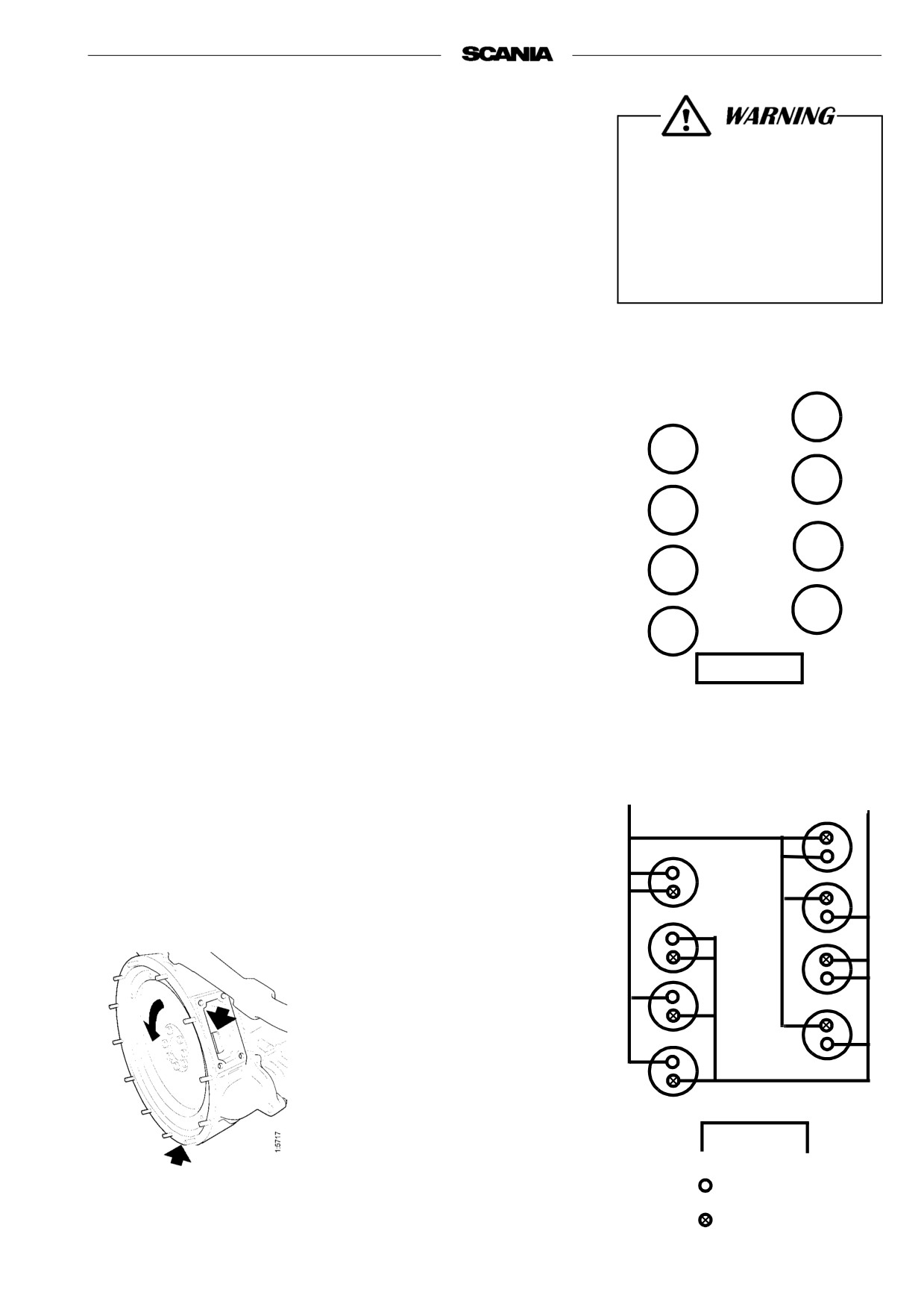
Alternative 1
- Turn the crankshaft in its direction of rotation until the piston in cylinder
No. 1 is 30°after TDC on the combustion stroke. There is a mark, ⊥, at
this position.
1
- Adjust the following valves:
5
Right side Cyl 1
Intake and exhaust
2
2
Ex
4
Ex
6
Left side Cyl 5
In and ex
7
In
3
8
In
7
- Turn the crankshaft one revolution in its direction of rotation to the
⊥ mark. The piston in cylinder No. 1 will then be 30°after TDC on the
4
induction stroke.
8
- Adjust the following valves:
FLYWHEEL
Right side Cyl 2
In
Cylinder numbering
3
In and ex
4
In
Left side Cyl 6
In and ex
No. 1 cylinder piston 30°after
7
Ex
TDC in
8
Ex
combustion
induction
stroke
stroke
Important.
On silumin housings, reading is possible
only from underneath.
On ductile cast iron housings, reading is
possible from underneath or from the
side (60°), depending on accessibility.
FLYWHEEL
Intake valve
Covers for reading
on flywheel casing
Exhaust valve
2001-05:1
47